
I am restoring a Yamaha CA 1000 and working on the power regulator circuit board. Can the 4 220uf 80 volt caps be replaced with 330uf?



Avionic, are you saying replace each with 2 1n4007’s in series? This one would power up on a dbt in normal mode, come out of protection and play via headphones after a heavy cleaning. Didn’t like in in class A which is why I am recapping. I have ordered the two switches and trimmers. Since I have it opened and replacing parts anyway, what else for good measure? I plan on keeping it. It was surprisingly clean with no visible damage. There was a crackling sound from the area of the power filters (like a leaky corroded cap) but they looked okay physically when pulled. Already ordered replacements. Damn, these are nice looking builds.https://www.datasheetarchive.com/pd...a84f58ea7b82f81a9175e763eae&type=M&term=10DC2
1N4007 X 2 meets or exceeds the 10DC's
I had 4 330uf 100 volt upw’s and was out of 220’s. I have another mouser order coming up so can replace with 220’s. If the 330’s would provide better filtering and not cause issues, would just leave them in.Yes, in this case they can (personally wouldn’t do it), please just make sure they have 80V or 100V rating, do not use anything lower than 80V, and try do not to go beyond 330uF, that might strain your rectifier diodes.
These diodes (D701, D702), based on the SM, are two half bridge rectifiers 10DC-2 and 10DC-2R. I am pretty sure they are 200V rectifier diodes, not sure about current rating, they should be okay with 330uF. Any particular reason you’re doing this instead of just 220uF 80V?
Are they shorted ? If not , don't piss with them.. If they are shorted . Then fashion 2 each 1N4007 diodes in either the common anode or the common cathode configuration. Which ever apply's to your app.are you saying replace each with 2 1n4007’s in series?
They test fine. I have seen multiple threads about addressing certain issues. The crackling noise could have been the switches arcing? I do plan on keeping this one so would prefer a one and done for the long term. So if certain parts are known issues no sense in not doing it now. This one has never been touched as far as I can see and very clean. It played through headphones on a dbt with a 100 watt bulb ~ 330mA line draw for a bit then one channel distorts and line draw starts climbing and I turn it off.Are they shorted ? If not , don't piss with them.. If they are shorted . Then fashion 2 each 1N4007 diodes in either the common anode or the common cathode configuration. Which ever apply's to your app.
Crackling noise is usually a sign of bad/old/cold solder joints, so a total reflow of everything is a must even if they visually look okay.They test fine. I have seen multiple threads about addressing certain issues. The crackling noise could have been the switches arcing? I do plan on keeping this one so would prefer a one and done for the long term. So if certain parts are known issues no sense in not doing it now. This one has never been touched as far as I can see and very clean. It played through headphones on a dbt with a 100 watt bulb ~ 330mA line draw for a bit then one channel distorts and line draw starts climbing and I turn it off.
I reflowed already, these boards looked pretty good. Btw, I have restored hundreds of vintage pieces, just not a ca1000. A number of CR’s, I mostly stick with Luxman, Marantz, Mcintosh and Sansui so I am not new to this. The noise came from down low, I thought from the bottom of the power filter caps. I now know about the class a/b switches so it was likely them as they are right there as well. I know enough to know what I don’t know and not afraid to ask questions. I have zero history on this unit. After I replace the switches and trimmers, will see if I can get stable idle/bias currents.Crackling noise is usually a sign of bad/old/cold solder joints, so a total reflow of everything is a must even if they visually look okay.
For caps, as was stated, if the size is not an issue, 330uF 100V will be just fine. The diodes, again as was stated, leave them alone if they aren’t causing trouble.
Btw, I have restored hundreds of vintage pieces …


I just wrapped up a full restoration on this one. The CA1000 is just in another league on build quality. If you want to challenge your skill set, take on a pioneer NSA. I have been looking at the new Yamahas, but where is the fun in that?
My apologies, didn’t mean it that way at all. I often come across cases, here and elsewhere, where individuals change tens of components at a time without ever checking or retouching the solder joints, connectors, switches, etc. and then wonder why so many things don’t work or don’t work properly … obviously not the case here. Nevertheless, if there’s anything I can help in my small capacity, by all means.
Enjoy the amp, one day I’ll give it a try too, I’m just not an integrated amp type, except for my Sansui alpha series amp that is.
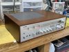
Looks great,I just wrapped up a full restoration on this one. The CA1000 is just in another league on build quality. If you want to challenge your skill set, take on a pioneer NSA. I have been looking at the new Yamahas, but where is the fun in that?View attachment 2833534
.
Are you tackling a CR-1020 next??I just wrapped up a full restoration on this one. The CA1000 is just in another league on build quality. If you want to challenge your skill set, take on a pioneer NSA. I have been looking at the new Yamahas, but where is the fun in that?View attachment 2833534
I have done 4 of the CR1020’s. The power supply’s will be shot. But these are really nice sounding units when finished. You need to pull the transformer out, but the wires are long enough so you can get it up and out of the way. That gives access to remove the regulator and cap boards. The low voltage section is rife with either a bad transistor or solder points. Just rebuild the whole section. You can then get at everything front side much easier as well. The amp sections come out fairly intuitively as well. Not the build quality of the CA-1000Are you tackling a CR-1020 next??
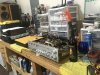
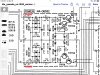

Update, I got the new switches installed. Fired it up on the dbt while watching the line draw and everything looked good. Went to mains power while monitoring line draw which is right around 300mA. Played via headphones fine. Measured DC at the speaker terminal with 15 mV on right and 60 mV on left. Noticed the line draw increasing rapidly after about 5 minutes and and crackling snap through the headphones with the selector in normal mode. The two side by side resistors (as far as I can tell 3.9 ohm 1/2 watt on the power regulator board are now black in the center and it won’t come out of protection. Line draw at 240 mV.
So obviously I still have some work to do. The output transistors stayed cool to the touch. So before I replace the resistors, what do I need to be looking at? Replace the trimmer resistors on the amp boards? Bias transistors? What else? Acting like a failing transistor when heating up? Something is shorting or demanding excessive current.View attachment 2842458
I replaced the two 3.9 ohm resistors on the power board and got a stable turn on and was able to set all the voltages quite easily while watching the line draw. Then after about 20 minutes while playing via headphones heard some crackles on both channels and then noticed the line draw increasing. Shut down. So sounds like all the FR’s need to be replaced and just a full rebuild of the power board. I want to keep this one. Damn this thing pulls som power in class A.Regulated power supply feeds function, tone, filter and power amp boards.
You can easily recheck FR401,2 FR301, R619(L&R channels), test in circuit, possibly one has started to drift high.
Certainly test FR703,4 on the power supply board, expect these to have been stressed.
Generally, the fault may be on the psu board, eg, protection circuit or one of the boards previously mentioned.
Unless one of the FR's has drifted high you may need to disconnect each board in turn by either removing the FR
or unsoldering the psu wire, eg, +/-50 on power amps., tone +B brown wire.


