
What should the line draw be on these when stable?



Less than the line fuse...What should the line draw be on these when stable?

Normal or Class A ?What should the line draw be on these when stable?
Certainly all the FR's should be checked, if they measure ok then it's pointless to replace. I've done 7-8 of these and sometimes they are ok and sometimes a 220ohm FR reads like 800ohms or open or...So sounds like all the FR’s need to be replaced and just a full rebuild of the power board
A nice amp when working normalI want to keep this one.
Bias 940mV in class ADamn this thing pulls som power in class A.
Both channels affected would point to psu. If you are able to reproduce the problem then monitor the +/-50 voltages on power amp boardsheard some crackles on both channels and then noticed the line draw increasing.
There is more going on than just the idle current. I am currently at 415mA with no speakers after about 30 minutes and headphones only playing via aux input. Normal mode. I want to make sure it’s stable before going class A. Although I did go to class A to set the current maybe 5 minutes on each channel. I always monitor the line draw for the first 10 hours or so looking for stability. My routine is to play with headphones and then do all the adjustments while monitoring the line draw. Then I shut down and let things set overnight. Then I play it for a bit and readjust after warmup. If the line draw is stable, ie goes up with volume and then drops to baseline at idle then just casually watch it while on speakers.I would think pretty close to your idle current setting.
Normal --- 47mv calc = 50ma
ClassA ----940mv calc = 1A
Certainly all the FR's should be checked, if they measure ok then it's pointless to replace. I've done 7-8 of these and sometimes they are ok and sometimes a 220ohm FR reads like 800ohms or open or...
A nice amp when working normal
Bias 940mV in class A
Both channels affected would point to psu. If you are able to reproduce the problem then monitor the +/-50 voltages on power amp boards

I don’t know what would have caused 701 and 702 to be open or why 703 and 704 to be 22 ohms? The solder points looked original and they were two different types of resistors.I pulled the noted resistors on the Power board and replaced them. It’s now acting stable @ 30 minutes+ with a predictable line draw and no crackles or runaway. I did measure them after pulling and they weren’t way out, but the schematic shows 704 and 704 at 47 ohms, but 22’s were installed. 701 and 702 were open. View attachment 2843798
I've had inrush issues with FR701,2 and one currently available FR, dismiss if yours were original. I have not seen any units with 22ohm at 703,4.I don’t know what would have caused 701 and 702 to be open or why 703 and 704 to be 22 ohms? The solder points looked original and they were two different types of resistors.
The solder points looked original? 702 and 701 were opened, replaced with 3.9 ohm. 703 and 704 were two different resistors, 703 measured a bit over 24 and 704 22.5. 705 measured 4.2I've had inrush issues with FR701,2 and one currently available FR, dismiss if yours were original. I have not seen any units with 22ohm at 703,4.
What is your serial number eg, 186xx or the power supply/relay board number NA-nnnnn? Yamaha would not have used different resistors so not OEM. Post a pix.

As far as I can read the micron is a 22The solder points looked original? 702 and 701 were opened, replaced with 3.9 ohm. 703 and 704 were two different resistors, 703 measured a bit over 24 and 704 22.5. 705 measured 4.2
View attachment 2844263View attachment 2844264
The micron certainly looks original. Reducing 47 to 22ohms allows for a higher (fusing) current from 100mA to 150mA. Odd that both the +ve and -ve supplies are changed. I get my units from Japan so they have a relatively low serial numbers, highest I've worked on is in the 13xxx's so a late change is possible. I'd need to know the Function, tone, power amp board numbers, would be nice to get the filter board but it's a PITA to get to so don't bother.


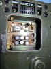

So what caused the audio crackle(dc offset) and the FR's to blow... enjoy the ampAll voltages/currents set spot on and stable. Main line draw stable at idle 406 mA and playing sweetly.

The normal/class A switches were shot? It’s stable now. The normal mode idle current trimmers are a bit sketchy, but the class A’s were solid? I bought bourns multi turns to replace, but I hate them and left the originals in. As with all the vintage Yamahas, power regulator boards need most of the attention. It’s been recapped mostly as well. I used UCC’s for the power filters.So what caused the audio crackle(dc offset) and the FR's to blow... enjoy the amp
25k serial number
https://audiokarma.org/forums/index.php?threads/yamaha-ca-1000-repairs-and-parts.929366/
suggest 22ohm is oem, google audiokarma yamaha ca-1000 22
Fingers crossed...The normal/class A switches were shot? It’s stable now
Very strange, the 3296P series is close to ideal drop in replacement and with a top adjuster...I bought bourns multi turns to replace, but I hate them and left the originals in.
I prefer the Nichicon UEP for the protection circuit, bit more robust than the UES or the film, it's only the protect circuit so no audio improvement.Yamahas, power regulator boards need most of the attention
+1, I'm generally happy with either the KMH and SMH series, haven't explored others (yet) from UCC.I used UCC’s for the power filters.


