

You are using an out of date browser. It may not display this or other websites correctly.
You should upgrade or use an alternative browser.
You should upgrade or use an alternative browser.
Yamaha CA-1010 Major Restoration
- Thread starter Will_Emanuel
- Start date
-
- Tags
- ca-1010 rebuild recap restoration yamaha
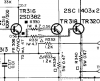
Yamaha often highlight the audio path, though it's not really visible on the hfe schematic, it's better in the hfe service manual if you look at the main circuit board schematic, still a struggle with a black and white copy. Extract below, note the arrow to the right of R331. This path includes TR301, TR308,9,7, TR316,7,8,9,,,Are there other components also in the Audio Path on these Main boards?

The emitter resistors I like to use Ohmite Audiogold series .
https://www.mouser.com/datasheet/2/303/res_audiogold-1280116.pdf
https://www.mouser.com/ProductDetail/Ohmite/AG5JR47?qs=XeJtXLiO41S/iglCIk%2Bp/g==
Athanasios
https://www.mouser.com/datasheet/2/303/res_audiogold-1280116.pdf
https://www.mouser.com/ProductDetail/Ohmite/AG5JR47?qs=XeJtXLiO41S/iglCIk%2Bp/g==
Athanasios
Slide 1-5 Soldering technique needs a little improvement
Slide 9.
Many diodes with lifted legs?
Not sure why you went with MKS(?) for C301,2 (1uf/80V) these appear to be a noise path for +/- rails, ie, not in audio path, a 15cent Nichicon UPW would have been fine. Likewise C321, 322. Expect some ripple on the unregulated supply, how does MKS handle ripply versus UPW?
Slide 9.
Many diodes with lifted legs?
Not sure why you went with MKS(?) for C301,2 (1uf/80V) these appear to be a noise path for +/- rails, ie, not in audio path, a 15cent Nichicon UPW would have been fine. Likewise C321, 322. Expect some ripple on the unregulated supply, how does MKS handle ripply versus UPW?

Just identifying it and what I would use. If you want to use wima films go for it..So not a good idea to replace with MKS?
No.Any advantage of one over the other?
Solder blob should be shiny and look a bit like a tear drop. The blobs on the trimmers are close, maybe just a bit too much solder.What do the deficient solder joints look like?
C104(220/6.3V) is a polar tantalum on the function board, audio path. Use either MKS2, Nichicon UKL both low noise or UFG if your not greatly concerned by the noise floor.I expected the Cap concern would have been C104?
Try to work out why Yamaha used "that" original part. Yeah sometimes it was basic costs but more often it was about selecting the best part for the job at hand. Ceramic discs have good RF properties, how does MKS2 compare? Seems to be a school of thought that all electrolytic caps under 4.7uf should be replaced with MKS2, even caps used in noise paths, protect circuit, meter drive and... where there will be no improvement to SQ.Cost of parts are not of concern to me on this project, more interested in perfor4mance.
Ceramic disk ---> NPO/COG
But it's your amp/refurb
Mostly just flux, needs some board cleaner, will look mostly ok.
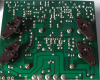
Nude power amp board (elec-caps etc removed). Don't have a close up...
I just use snipping tool on my laptop rather than uploading the entire file. Hi-res comes out high res...I have been struggling with "Upload a File" with it's file size limitation. What is the maximum resolution that a photo can be shot at and uploaded?
Nude power amp board (elec-caps etc removed). Don't have a close up...
Schematic shows 100uf/6.3V however my notes show 10uf/16VSorry I meant C304
Serial Number 38xx had 100uf/6.3V while SN 13xxx has 10uf/6.3V
Audio path input to power amp, I'd use audio grade something like Nichicon UKZ, UFG or Elna Silmic II
I didn't check all, did the first 6-7, audio path is shown in the service manual power amp schematic. Also shown at a high level in the block diagram.ALL Components in Audio Path?
I wish...I have a HP204C & HP334A
Yeah, distortion measurement is a good start. Needs a "pure" source/signal generator and equally good (calibrated...) distortion analyzer. Most would simply check distortion at the speaker posts and only investigate further if measurement was out of spec
Truthfully, I don't have any at this time. I'm on a tight budget struggling to save up for a Sansui alpha, and living in a country where such equipment is not dumped on the kerb. Yeah I've seen new units but still looking at $400-600AUD. I've recently purchased a new/higher spec sound card and plan to use freeware, maybe REW? But it's still just a toy, only as good as the sound card.Cost effective recommendations?
Bit of a loaded question. I picked up a vintage Electrocompaniet 1a pre for parts and managed to get working (for a while at least). Yeah, interesting sound but at times I thought I was missing something. Think Electrocompaniet were one of the early ones to extol second order harmonics over third etc... I certainly don't have the knowledge to tweak something like a CA-1010 to bring out the more favourable second order or further attenuate the third order, I participate on AK to learn that kind of sh#t, so outside my sphere of influence, so as long as they are 100+dB down...How do you put a value on 2nd, 3ed and 4th order harmonics?
For basic adjustment of MC stage according to SM. Are you asking what is an acceptable 2nd, 3rd,,, order harmonic?I guess this answers this question?
I didn't see any measurements on the power amps that confirmed this. Also, maybe start a new thread on this. Measure Vdc at left power amp TP1 (to GND) repeat for right channel. Should be less than 100mV, probably bouncing around based on post #65.I am being told that I have DC on one or both Main Boards.
Measure Vdc at TR316b/D306 anode, repeat for TR317b/D307 cathode.
Not to be confused with the 1A fuses? I have the Japanese CA-1000IIIFound both 10A fuses in the Normal PS blown
F401 0.5AT
F402 1AT
F403 1AT
F404 1AT
F405 1AT
F406 1AT
Which fuses were blown, F40x?
+/-BL, +/-B voltages ok?, check on both power ampsReplaced both fuses and now have 475mv on both Left and Right, neither one is adjustable with VR

OK, fuses for unregulated supply, makes more sense now, different transformer taps selected for class A/Normal by operations switch/relay. Check voltage at red (B+) wire, expect +22V in class A and +55V in normal.Located on the bottom side. The fuses that protect the Red power wires