• The move to the new server is done. There are some software and database maintenance updates in process. This has us passing the hat around to help out. We appreciate any donations. Seriously, even a dollar helps. The payment page may be found here - https://www.audiokarma.org/support.html

Yamaha CA-2010 Restoration

MikeC3PO

AK Subscriber
Subscriber
Hello Everyone;

I'm finally starting the restoration on my CA-2010. This is only my second full restoration. I've been reading lots and developing my skills with various repairs. Between the repair work and the restoration of my current workhorse CA-1010, I feel confident that this project will turn out great. Defiantly going to take my time with it and go for a fairly deep dive. Starting this thread as a place to seek advice from our great community and hopefully avoid a few missteps if possible.

High level plan is new electrolytics, relays, trim pots, fusible resistors, mica's / thermal paste for heat sunk transistors and a deep clean on all switches / pots including the sealed volume pot (more on that). May have to replace the snap switches also.

This unit is cosmetical near perfect, and I want to provide as good of a restoration as possible. I don't see any evidence that its been opened in its 45+ years.

My initial evaluation reveled the following:
-Initially audio from the right channel was muffled, tracked this down the the mute switch (it wasn't really working at all, worse on the right), gave it a quick D5 spray and this issue cleared up completely, so that switch will get a disassembly and deep clean (as will all the switches). Mode selector was a little scratchy also.
-Power switch is working but not 'snapping' upwards / on as clean or with as much authority as my CA-1010. Likely hasn't been used in a very long time, but this is a flag for replacement.
-Bias and DC offset seam OK, other than the fact that those old trim pots are brutal. Right amp might be taking slightly longer than left to settle down. At the moment I'm not going to worry about this too much as I'll be changing so many components. Please chime in if I should dig into this deeper before getting into the boards. Just a note for anyone on a similar journey, those test pins might need a little cleaning before testing on an untouched unit like this. Was hard to get accurate mV reading on the oxidized pins.
-Unfortunately the volume pot it scratchy. This is the part of the project I'm most nervous about. Never opened one of those sealed pots before.

Next will be some more disassembly, pictures, and some cap selections so that I can get a Digikey order in.

Please feel free to chime in with any flags or ideas. I'm very much just learning as I go here, but having fun while doing it. Thanks all.

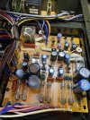
IMG_2045.jpeg
 
Register to hide this ad
Hello Everyone;

I'm finally starting the restoration on my CA-2010. This is only my second full restoration. I've been reading lots and developing my skills with various repairs. Between the repair work and the restoration of my current workhorse CA-1010, I feel confident that this project will turn out great. Defiantly going to take my time with it and go for a fairly deep dive. Starting this thread as a place to seek advice from our great community and hopefully avoid a few missteps if possible.

High level plan is new electrolytics, relays, trim pots, fusible resistors, mica's / thermal paste for heat sunk transistors and a deep clean on all switches / pots including the sealed volume pot (more on that). May have to replace the snap switches also.

This unit is cosmetical near perfect, and I want to provide as good of a restoration as possible. I don't see any evidence that its been opened in its 45+ years.

My initial evaluation reveled the following:
-Initially audio from the right channel was muffled, tracked this down the the mute switch (it wasn't really working at all, worse on the right), gave it a quick D5 spray and this issue cleared up completely, so that switch will get a disassembly and deep clean (as will all the switches). Mode selector was a little scratchy also.
-Power switch is working but not 'snapping' upwards / on as clean or with as much authority as my CA-1010. Likely hasn't been used in a very long time, but this is a flag for replacement.
-Bias and DC offset seam OK, other than the fact that those old trim pots are brutal. Right amp might be taking slightly longer than left to settle down. At the moment I'm not going to worry about this too much as I'll be changing so many components. Please chime in if I should dig into this deeper before getting into the boards. Just a note for anyone on a similar journey, those test pins might need a little cleaning before testing on an untouched unit like this. Was hard to get accurate mV reading on the oxidized pins.
-Unfortunately the volume pot it scratchy. This is the part of the project I'm most nervous about. Never opened one of those sealed pots before.

Next will be some more disassembly, pictures, and some cap selections so that I can get a Digikey order in.

Please feel free to chime in with any flags or ideas. I'm very much just learning as I go here, but having fun while doing it. Thanks all.

View attachment 3693789
Follow this: Project: Yamaha CA-2010
 
Absolutely! Thanks for mentioning that thread. That's one of my main resources (so I'm not bugging these guys all the time :) ). Eternally grateful to @Super Noob for that one.

Got my first parts order in (Cornell Dubilier Filter caps, Nichicon UPW / UPE and relay for the Power Board). Still need to do some disassembly, I've been having too much fun with some new to me PSB Avantes with this amp from the test bench.
 
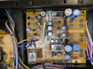
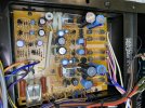
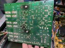
Taking a look at the power board, I did find some capacitor values that differed from the schematic and even Super Noobs build (Super Noob found C403 as 10uf, same as schematic, I found 22uf). I will replace with 22uf.

Also a few of the capacitor rated voltages were higher in my amp. C409, 410 found at 25 vs 16v. C425, 426 found at 50 vs 25v. C427, 428 found at 50 vs 35v. No worries here all cap voltages will be higher anyways.

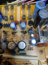
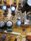
The one concern I do have is with TR 409 and R434. Looking real toasted. Also R434 looks like a 1/2w, expected a 1/4. Maybe someone has been in here?

Aside from cleaning this area up, and potentially testing those components, should I be looking to do anything else? Replace them? Try to determine why they got so hot? Run the amp for a while to see if they are still getting too hot?

Anyone see anything else concerning before I recap this board?

IMG_2057.jpegIMG_2058.jpeg
img_2059-jpeg.3697149


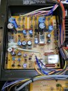
IMG_2060.jpegIMG_2061.jpegIMG_2062.jpeg
 

Attachments

  • IMG_2059.jpeg
    IMG_2059.jpeg
    173 KB · Views: 159
I see at least 7 or 8 of those e-caps that are due replacement. I would do a total recap on that PS/relay board.
Look at the shrunken vinyl sleeve's on the capacitors.

Those two, heatsinked pass transistors, normally run hot! Hence the reason for a heatsink. ;)

That transistor next to the oversized, replacement, resistor might have issues.
 
Last edited:
On the heat sunk tranny's I would put a spacer under the heat sink to raise it up off the board to minimize anymore
cooking of the board and it will allow a little air flow under the heat sink for better cooling.

Some one was in there, that light blue resistor was a replacement from a repair .

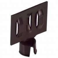
If the T0-92 tranny's get hot they make slip on heat sinks for them you could try.
pic has link ;)


Athanasios
 
On the heat sunk tranny's I would put a spacer under the heat sink to raise it up off the board to minimize anymore
cooking of the board and it will allow a little air flow under the heat sink for better cooling.

Some one was in there, that light blue resistor was a replacement from a repair .

If the T0-92 tranny's get hot they make slip on heat sinks for them you could try.
pic has link ;)


Athanasios
That TO-92 should not get that hot!
 
I see at least 7 or 8 of those e-caps that are due replacement. I would do a total recap on that PS/relay board.
Look at the shrunken vinyl sleeve's on the capacitors.
Total recap of this board / changing the relay happening!
That transistor next to the oversized, replacement, resistor might have issues.
That TO-92 should not get that hot!
What's the move here? I was planning to replace TR 409 with a KSA992, but is this issue likely limited to the transistor itself or should I be digging deeper?
On the heat sunk tranny's I would put a spacer under the heat sink to raise it up off the board to minimize anymore
cooking of the board and it will allow a little air flow under the heat sink for better cooling.
That's a great tip, thanks! I'll get a little washer or two in there between the board and the heat sink
If the T0-92 tranny's get hot they make slip on heat sinks for them you could try.
pic has link ;)
Thanks for that link, I can pop a couple of those on TE408,9,10 & 11 for safety, once I know everything is working as it should.
 
I checked before replacement and got:
E:-32.28V vs -32.2 schematic
C: -49.6V moving around a little maybe +/- 0.2v vs schematic -48.4
B:-32.88V vs schematic -32.8

Will replace and re-check.
 
I checked before replacement and got:
E:-32.28V vs -32.2 schematic
C: -49.6V moving around a little maybe +/- 0.2v vs schematic -48.4
B:-32.88V vs schematic -32.8

Will replace and re-check.
Your voltages look fine. So I'm doubting replacing the transistor will fix the issue. But stranger things have happened.
 
Your voltages look fine. So I'm doubting replacing the transistor will fix the issue. But stranger things have happened.
Maybe there is no longer an issue to fix? When I was cleaning the board up I noticed that the char seams to be equally centred around the resistor that was replaced in the past. Maybe this is just residual char from an event that lead to the previous repair? Either way I’ll get this board recapped and all cleaned up and take it from there, unless anyone sees any red flags.

The cap behind this tranny was running super hot for sure (about 55 deg C). TR 409 itself was around 44C.
IMG_2068.jpeg
 
Both resistors are still measuring within spec out of circuit. :thumbsup:

Thanks for commenting re carbon vs metal film. Was wondering about that.

I’ll replace the big one with a 1/2 watt that’s on its way.
 
What?
R434 the replaced burnt one. What did it measure? I'd use a 1/4 watt. It will fit better on the circuit board.
R434 the replaced burnt one, measures at 562.9ohms.

Will replace anyways with 560 ohm 5% that fits better.
 
Last edited:
New transistor and resistor installed. New thermal compound for heat sunk transistors (plus lifted from the board a little).

New TR409 running cooler.

Full recap next. image.jpg
 
Im running my CA-1010 now. I did one board at a time. Test.

Relays, Switches, and wafer switches were buggers. The pots should be fine with a spray.

I left the original bulbs. Not a fan of leds but that is preference.

Caps in general tested fine aside from the purple caps. All were replaced anyways.

Good luck with it. I SOLD EVERYTHING BUT MY 1010.
 
Back
Top Bottom