
Preferably without the dimbulb. Measure the DC voltage at the cathode end of D806. Should be a steady 31v +/- 10%.How would I go about testing a zener with a DMM?
Just in case.
Last edited:


Preferably without the dimbulb. Measure the DC voltage at the cathode end of D806. Should be a steady 31v +/- 10%.How would I go about testing a zener with a DMM?
Yes. Correct orientation on all of them, resistance looks fine between terminals. Is it safe to take it off the dim bulb for that zener? The highest voltage I’m seeing at the main board pots is -12V for VR702 so I’m worried something’s gonna give wayHave you already replaced the electrolytic caps? C814 - 816?
That's why you have 14v at the emitter of TR802reading 15.7V
Coupler switch flipped to on position, no difference in the dim bulb. Just to be clear, that 15.7V from the zener while on the dim bulb doesn't bode well?Without speakers attached. Disconnect the pre-amp from the power amps with the rear panel coupler switch. Power up with the dim bulb. How does the dim bulb react?
No it doesn't. I'd measure it without the dim bulb. With mini-grabber test probes. Or.. You can just replace the diode with a new one.Coupler switch flipped to on position, no difference in the dim bulb. Just to be clear, that 15.7V from the zener while on the dim bulb doesn't bode well?
Without dim bulb, I'm getting 32.9V. I'll get that new zener orderedNo it doesn't. I'd measure it without the dim bulb. With mini-grabber test probes. Or.. You can just replace the diode with a new one.
You don't need it. That zener is working. I think the dim bulb has been forking with you the whole time. What voltage do you have at the emitter of TR802 without the bulb?Without dim bulb, I'm getting 32.9V. I'll get that new zener ordered
31.8V at emitter of TR802.You don't need it. That zener is working. I think the dim bulb has been forking with you the whole time. What voltage do you have at the emitter of TR802 without the bulb?
Bingo.31.8V at emitter of TR802.
About that.. transformer voltages look good, +12, +12M, +12R, +30 all look good, +/- BR sitting at their respective 39V, but +/- BL giving me 400mV on the positive side and nothing on the negative. Right channel offset stuck at rail voltage. Left channel offset stuck at 78mV. 0V on either channel’s bias.Time for and audio test. After resetting the bias/idle current while on the straight mains voltage. No bulb.
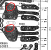
Left channel amplifier rails.but both fuses are blown
Both channels have been recapped. Left channel on continuity mode between collectors and chassis are reading in the hundreds of mV range while right channel is sitting cleanly 0LLeft channel amplifier rails.
What all has been done to the left channel power amplifier?
Measure the resistance between the output transistor (case) collectors and chassis ground. Without power of course.

Both channels have been recapped. Left channel on continuity mode between collectors and chassis are reading in the hundreds of mV range while right channel is sitting cleanly 0L

Not good, need to investigate.Left channel on continuity mode between collectors and chassis are reading in the hundreds of mV range
Ohms mode, got it. Right channel climbs up and maxes out pretty quickly, left channel stays around 1k ohmsHe asked for resistance, not voltage . With power off .
Pull F801,F803 and repeat measurement, still expect 1kRight channel climbs up and maxes out pretty quickly, left channel stays around 1k ohms