• The move to the new server is done. There are some software and database maintenance updates in process. This has us passing the hat around to help out. We appreciate any donations. Seriously, even a dollar helps. The payment page may be found here - https://www.audiokarma.org/support.html

Yamaha newbie A-700 resto thread

Luckily I haven't had a problem with those switches yet. I just squirt Deoxit5 in the center spring hole area and push the switch ten times or so. I clean all the controls before doing anything on an old piece. Even before 1st power up. I don't mind standing alone on that. Rarely have to replace a switch.
That's the first thing I do too, I just figured I would try to really clean them based on suggestion here but getting it back together was way trickier than I anticipated. Two of the switches were victims of my shaky hands, and the tiny internal pieces got bent to an unusable state. lol.
I had a similar problem with my CX-600. The new switches that I bought had a shorter body.
I added longer legs from snipped off cap leads and cut plastic blocks for a base.

View attachment 3144795View attachment 3144796View attachment 3144797View attachment 3144798View attachment 3144799

Cheers,
James
Where did you get the plastic you used? 3D printed? That's exactly the solution I will need to use, thanks for the visual aids!
 
That's the first thing I do too, I just figured I would try to really clean them based on suggestion here but getting it back together was way trickier than I anticipated. Two of the switches were victims of my shaky hands, and the tiny internal pieces got bent to an unusable state. lol.

Where did you get the plastic you used? 3D printed? That's exactly the solution I will need to use, thanks for the visual aids!

I hand cut with a fine blade hacksaw from a block of PVC that I had on hand and then used a fine file to make space for jumpers etc.

James
 
I hand cut with a fine blade hacksaw from a block of PVC that I had on hand and then used a fine file to make space for jumpers etc.

James
I have a file and a drill, I'll go to the hardware store after work today and see what I can figure out. I reckon I can just poke the legs of the switch through a piece of paper to use as the drilling template on the piece of plastic. Thanks for the idea!

You could use old credit cards stacked and glued together . :D

I save mine for such situations

Nashou
I think I've only had to get rid of an old/expired credit card 3 or 4 times at this point in my life... :biggrin: but good to remember for the future!
 
I have a file and a drill, I'll go to the hardware store after work today and see what I can figure out. I reckon I can just poke the legs of the switch through a piece of paper to use as the drilling template on the piece of plastic. Thanks for the idea!


I think I've only had to get rid of an old/expired credit card 3 or 4 times at this point in my life... :biggrin: but good to remember for the future!
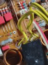
I don't recall the hole spacing right off hand but the datasheet shows them.

Since I just soldered the leg extensions face to face on the original legs I was a bit concerned about them coming loose when I soldered the switch to the board. So I drilled the holes small enough that it was a "push fit" getting the legs through the block.
I figured that was even if the solder melted there would be no place for the legs to go and they would resolder when it cooled.
In the end there were no problems.

Do you have a set of calipers? I highly recommend a set of good calipers and a couple of sliding 45/90° squares for your toolbox. They make it very easy to mark and scribe measurement positions on just about anything. Having 2 sliding squares is handy when marking several different holes along a line.

DSC02192.JPG

I have been using dial calipers for so long I actually prefer them over digital. Mitutoyo are a bit expensive but are very good, the kind of tool that lasts a lifetime if taken care of.

James
 
1000008779.jpg

Here's the transistor that gave some magic smoke. It's definitely seen better days. The other legs mostly just crumbled away when I desoldered them.
 
Well, upon further fine-toothed comb inspection, I found something that I did wrong when I first put it back together.

1000008780.jpg

Left and Left Earth going from the speaker selection board (Main 6) to the main amp board are wired correctly. I assumed since the left channel was correct with the black stripe/lettering half of the cable, then the right side would be the same.

I was getting continuity between ground and the right speaker terminals, so I was tracking down "why" and got to this wiring... The other side of the yellow wire, on the speaker selection board has the black stripe/lettering going into L and the blank side going into LE, but the right channel has the blank side going into R and the stripe/lettering side going into RE. I should've checked closer on re-assembly but again, I didn't touch the other side of the yellow wire at all so I assumed it'd be the same for both channels. Blah. Could this have been the problem with my no left channel? It makes no sense to me, though...
 
1000008798.jpg

Digikey order delayed a day (as always) so working on some upgrades to the KA-7300 tonight. My soldering has come a long way in only two months, some of these solder joints I did are very questionable, lol.

Worf looks like he's lusting after the Kenwood! :biggrin:
 
My soldering has come a long way in only two months
Re-capping is good practice eh? 650-700 degrees F seem to be ideal per the pros. Works well for a quick in & out time on those small components that heat up fast. I've cooked out the electrolyte within small size electrolytic caps before in 3 seconds. Body of the cap had slimy goo on it. Re-replaced it. I aim for 2 second heat time on small parts. Solder bond should look shiny when complete & not dull; though many pieces have dull solders and pretty much work, lol. Semiconductors are really heat sensitive.
One newbie to another.
EDIT: heat the component not the pad. Let er flow down with heat source above.
 
Last edited:
Re-capping is good practice eh? 650-700 degrees F seem to be ideal per the pros. Works well for a quick in & out time on those small components that heat up fast. I've cooked out the electrolyte within small size electrolytic caps before in 3 seconds. Body of the cap had slimy goo on it. Re-replaced it. I aim for 2 second heat time on small parts. Solder bond should look shiny when complete & not dull; though many pieces have dull solders and pretty much work, lol. Semiconductors are really heat sensitive.
One newbie to another.
Don't forget the flux. Solder, especially old solder, melts faster with it.
 
Digikey order came today.

1000008818.jpg
I was not expecting this to be so tiny, lol. But it's not about the size, it's how you use it, right???? LOL. Gonna do some reading on how to use it and practice on some kits I have, it's all been flux with the desoldering vacuum tool for me so far.

1000008819.jpg
@Soundscape these are the resistors I got based off your rec. 470 ohm 2W KOA Speer. I hope these will work.

You said they go across emitter and base. So I just put these there instead of the four devices mounted on the heatsink, or just the bigger MT200 ones?

If I reinstall everything else with these resistors in place, and nothing goes pew pew smoke smoke (and voltages test good, lol) then I should be good to put the real things in?

Obviously all on the DBT, I am traumatized and will never take anything I'm working off of one again until I'm absolutely sure it's ready.

I've been researching oscilloscopes. Seems like the always recommended in the past analog ones are getting just as expensive as entry level new digital ones. I still want an analog one, though. Probably Tektronix, probably refurbished. I'd hate to have to try and repair a repair tool, lol.
 
1000008821.jpg
Already had flux paste on hand, btw.

Someone here also told me early on that applying new solder to old joints can help with desoldering and that was a great tip I would've never thought of. :biggrin:
 
Put the 470 Ω resistor only on the outputs as those are the ones that are hardest to find and replace and most expensive . For the driver transistors you need all those in place for testing of bias and DC offset adjustments .
 
If I reinstall everything else with these resistors in place, and nothing goes pew pew smoke smoke (and voltages test good, lol) then I should be good to put the real things in?
Should be. We're gonna de-solder all 3 output transistors leads and place your resistor on the board pad, emitter to base, collector pin left open. Test for D.C. Voltage at resistor and at collector pad. I'm not sure what a good VDC reading would be on your piece at this time, I haven't downloaded your service manual. I usually just dummy out the bad channel side, Left or Right. Most problems are one sided.
470 ohm 2W KOA Speer. I hope these will work
Those are fine. Good luck champ.
 
Back
Top Bottom