• The move to the new server is done. There are some software and database maintenance updates in process. This has us passing the hat around to help out. We appreciate any donations. Seriously, even a dollar helps. The payment page may be found here - https://www.audiokarma.org/support.html

Z19 Crossover

No prob - I think I will leave the schem drawing as is for now.

Please look it over - I can make all additions at one time.


I found Zilchs discussions on the z-19 model 19s and Valencias about two weeks before he passed.
At the time I had just bought a set of Heathkit 101s for my dad. They needed recap and all roads lead to Zilch when you google those Altec items.

I am back to basic/stock but new capacitors and I found zilch's Z-19 schematic on another site. I couldn't sort out the L pad stuff well enough and then - I found this link. The drawing gave insight but there were a few things missing that I needed. I don't have alot of crossover build exp -

There are great parts lists and discussions on what to buy and add together for this upgrade.

I will be using a 7.0 oil capacitor and a 1.2 WIMA MPK to make 8.
A 20 Mf oil and a 1.2 WIMA for the 21.

The Heathkits sound great with stock values - however the LPad s first quarter turn seems to be where any horn control is...not much change after that.

I think the dual Mid/High control will help fine tune.

Thanks for the compliment Zonker
I'll put a note in the margin about Capacitors and combination of values.

Cant wait to build now.

Oil, should sound nice!:thmbsp:
 
No, no, no need for sorry! Learning is what this is all about, I'm just here to "point out the obvious". That it's not obvious to everyone is part of the learning curve. It wouldn't look obvious to me if I hadn't had it pointed out countless times by those who knew...

Thanks, 4343! But I was apologizing not only to you, but to Billy for misdirecting his efforts; anyway, yes, this is how I learn! :)

And yes, the 21uF is another case of an odd value (unobtainium probably) being made up from the common values you see on the parts list, but NOT the schematic. Thanks for pointing that out, I missed that... Goes to my point that that drawing was not intended to replace the schematic, it's a _parts placement_ drawing.

I definitely get the schematic / layout distinction. Perhaps later we can start a new DIY thread that simply lays out, in terms even I can understand, what to buy and how to build it. This thread contains all that information, but I think it could be condensed into a nice Cliff's Notes version. Billy's drawing will be a huge help in that direction.
 
My search didn't find it, and I hope this isn't buried somewhere in this thread (I've been through it so many times I don't want to read it again), but:

Has anyone used bypass caps on the capacitors in the Z19 signal path (they would be the ones on the horn signal path)? If so, which caps did (or would) you put them on, did you like the results, and which caps did you use? Thanks.
 
Last edited:
Typically your bypass cap is 10% of the tweeter cap value. I would use it on both sides of the horn network.
DC
 
In measuring these samples, my criterion was flat within +/- 2.5 dB. DE250/152i appears among the flattest responses across the widest SPL range (12 dB) with it, actually. The peak at 2 kHz suggests that the core 3rd-order highpass (C2, L2, C3) is somewhat underdamped with that combination, which could be easily resolved in PCD for a final design, if desired:

attachment.php


Getting back around to my crossover adventures...can someone explain how to resolve the "underdamped" issue? What am asking is, what general direction(s) (and magnitude) should C2, L2, and C3 be changed to flatten out the curve? My PCD skills aren't up to the task of setting up the model but I can plug in numbers if someone can get me started. Any help is appreciated...I'd like to avoid randomly changing parts and testing.
 

Attachments

  • DE250 152i.JPG
    DE250 152i.JPG
    49.7 KB · Views: 30
Just wanted to share, I built a pair of Z19 crossovers. I have a pair of custom cabinets (20 x 20 x 30), Altec 416 and Renkus-Heinz 2" high-compression drivers. I used to drive these with an active crossover and two amps before I built these. Should have built them sooner, they really improved my system.


My requirements were:
- having a crossover enclosure as I wasn't going to drill into my speakers, and there is no provision for a crossover on the speaker enclosure. This would allow the crossovers to live on top of the speakers safely.
- having a terminal strip for inputs/outputs to secure and clean up the connections
- using "budget" components (which still ended up costing around $220).


I used Radio Shack 6x9 inch perfboards as the base (although it could have been plywood or just about anything else). There is wiring underneath connecting various components to each other. I also used terminal strips to ease joining multiple connections and to connect the L-pads.

My guide was the drawing from post 229 as my guide (see link). I didn't follow it fully, but it was a very useful starting point.
http://www.audiokarma.org/forums/showpost.php?p=4515497&postcount=229

My BOM is from post 15 (see link), note that some of the caps are paralleled to reach the correct value.
http://www.audiokarma.org/forums/showpost.php?p=4086331&postcount=15


More info in this thread: http://www.audiokarma.org/forums/showthread.php?t=365108


attachment.php


attachment.php


attachment.php


attachment.php
 
Last edited:
Getting back around to my crossover adventures...can someone explain how to resolve the "underdamped" issue? What am asking is, what general direction(s) (and magnitude) should C2, L2, and C3 be changed to flatten out the curve? My PCD skills aren't up to the task of setting up the model but I can plug in numbers if someone can get me started. Any help is appreciated...I'd like to avoid randomly changing parts and testing.

That's a great question, Don. I would like to understand more about this myself. Bump.
 
Thanks!


The cabinets are approximately 20 inches wide, 20 inches deep and 30 inches high. They lived for about 40 years inside of a wall in a studio in Paterson, NJ (with only the front baffles peeking out of the wall).


Kansei,
Do you know what studio they were installed in?
Might be interesting historically.
 
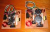
A pair of Z19s I built for rswojo. They're going out to him next week.
attachment.php


These were built completely point-to-point, with as few jumpers or solder connections as could be done. In fact, other than one jumper per L-pad, there ARE NO other jumpers required- everything was done with the lead of one component, DIRECTLY soldered to the lead of the next component, without having to add any extensions.

Yeah, it's a little more cluttered than the circuit board or terminal strip approach... but this way is GUARANTEED to have the best electrical connectivity, pretty much inherently. Less lead length, less connections, all connections directly made == better signal path...

All three caps in-line with the horn have been bypassed by polystyrene .01uf caps, a la JBL practice in their higher-end home speakers. With a horn as revealing as these, it's good practice...

The wiring on these is Audioquest FLX14.4 14g wire. Good stuff, and should last forever. I tried to use the factory Altec color codes- the only variation is a white wire (instead of black) for the horn negative lead (since that was what was in the FLX14.4... one red and one black, used for the woofer, one green and one white, used for the horn)...

Now, to pack 'em up!

Regards,
Gordon.
 

Attachments

  • z19_xovers.jpg
    z19_xovers.jpg
    77.6 KB · Views: 447
...and after a brief break, Z19 crossover development continues. Can anyone measure and post the dimensions of a stock Altec Model 19 crossover board? In an ideal world we should be able to build this up and drop it in as a substantial improvement in place of the stock board. :scratch2:
 
I posted pics of a Z-19 assembled on a stock 19 plate.....I know it was over in LH and I posted here. See if I can find it. You can get everything to fit, it is a squeeze!
DC
 
Thanks DC. In the chaos that resulted after Zilch's passing and the rescue of the lab, I'm having a hell of a time putting my hands on a stock example of the Model 19 crossover but really want to keep the ball rolling. It's what Zilch wanted.:thmbsp:
 
Something that would be a great addition to the Zilch legacy would be a version tuned to use the 931 MantaRay horn and a 12" woofer (like the 414) in a Model 14 clone. I have the parts to build 19s, but no place to put the resulting refrigerators.
 
That's a great idea, having it fit "drop in." :thmbsp:
That stock M-19 x-o Zilch used to use for development has got to be somewhere, but I can only imagine how difficult it is to find stuff.
Someone out there has to have one right in front of them, ready to be measured for dimensions.
 
Back
Top Bottom