• The move to the new server is done. There are some software and database maintenance updates in process. This has us passing the hat around to help out. We appreciate any donations. Seriously, even a dollar helps. The payment page may be found here - https://www.audiokarma.org/support.html

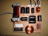
Z19 Crossover

Those look pretty good. I was going to pay somebody to build them but there are only two guys who do this where I live and both said no. So I am going to do it myself. I like the connections on that board.
I hope mine look half as good.

They were done by Bob Crites. He has a web site you can look at. He offered a suggestion on a parts list that would reduce the build cost. Every thing was done over the internet and through the mail.
 
All the parts are in; that was fast. I actually ordered my caps from Madisound as they had some of the exact values so the total part count (and cost) will be lower.

I went with Solens Caps and Mills Resistors. Stopped by home depot today and bought a 8" x 12" x 1/4" piece of hobbyist oak to assemble the crossovers on. I figured oak would be fitting as my Altecs are Oak. :thmbsp:
 
All the parts are in; that was fast. I actually ordered my caps from Madisound as they had some of the exact values so the total part count (and cost) will be lower.

I went with Solens Caps and Mills Resistors. Stopped by home depot today and bought a 8" x 12" x 1/4" piece of hobbyist oak to assemble the crossovers on. I figured oak would be fitting as my Altecs are Oak. :thmbsp:

All my parts came from Madisound too. Good luck on the build.
 
Last edited:
Z19, marantzfan style...

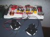
Got these finished tongiht. I laid them out a little differently then the model earlier. I am just about rounding third base on getting my Model 19's finished.

What do you think?
 

Attachments

  • DSC00283.jpg
    DSC00283.jpg
    79.4 KB · Views: 389
  • DSC00284.jpg
    DSC00284.jpg
    87.8 KB · Views: 456
Got these finished tongiht. I laid them out a little differently then the model earlier. I am just about rounding third base on getting my Model 19's finished.

What do you think?

Those look great. What kind of wire are you using inside the 19's?
 
What can I say, but that they are beautifully built in the finest DIY tradition I have attempted to teach here. ;)

Now, if only they work as nicely as they look, that's icing on the cake...! :thmbsp:
 
Last edited:
What can I say, but that they are beautifully built in the finest DIY tradition I have attempted to teach here. ;)

Now, if only they work as nicely as they look, that's icing on the cake...! :thmbsp:

Now, the only thing I am not sure about is which terminals are which on the stock original M19 lpads.. :scratch2:
 
Look VERY closely, with a magnifier, if necessary. The middle one is #2.... :yes:

I removed one of the lpads and looked closely under bright light and I can't see any markings at all anywhere. Can you post a pic of yours showing which terminal is which?
 
I ordered all my parts today. Another AK'er has generously offered to build these for a very low cost but I think I am going to try this myself.
The only glitch is Parts Express charged me $50 to USPS to Canada!
 
This is not an E-Wave crossover substitute. It is suitable for use in some premium and uber-premium EconoWave designs by those who understand it, and as a developmental tool for those defining new ones.

It's primary use is in upgrading vintage Altec 2-ways....
And what a upgrade it is:thmbsp:. I replaced my N-800-D XOs in my VOTTS with these one night because I was bored and they will probably never be taken out. My VOTTs have never sounded so good. Mine are a bit ugly and maybe someday Ill clean them up, until then Ill just enjoy them:yes:. Thanks Zilch!!!
 

Attachments

  • picture 005.jpg
    picture 005.jpg
    69.3 KB · Views: 265
It is just so cool that you're posting all this stuff, Zilch! :music: I have stared and stared at the schematic and the circuit board layout, and formulated my own parts list, and I'm starting to wrap my head around this, but one thing keeps driving me nuts: At the bottom right of the circuit board you have three resistors (R1, R2 and R3) all connected to each other at one end. But no matter how much I cross my eyes I can't reconcile it with the schematic, where they are separated from each other by the midrange L pad.

I know I'm just being stupid, but is that right, or is the circuit board different somehow?

attachment.php


attachment.php


attachment.php


I might dumb down the layout even more for idiots like me (and to verify my own understanding), and post a drawing with all the shorthand part numbers ("R1," etc.) written in. You're going to be selling these, right? I'm still trying to decide whether to make my own. If I'm understanding the board correctly, and with all your great photos and drawings, it looks doable to me.
 
Last edited:
R1 and R2 are wired series across C4, the center point between those 2 resistors connects to terminal 1 of L-pad 1. Terminal 2 of that L-pad goes to ground through R3. Only one side of that L-pad is used.

Hope that helps.
 
Got these finished tongiht. I laid them out a little differently then the model earlier. I am just about rounding third base on getting my Model 19's finished.

What do you think?

Looks good! Can u take a pic of the back of them? are u using L pads for anything?
 
R1 and R2 are wired series across C4, the center point between those 2 resistors connects to terminal 1 of L-pad 1. Terminal 2 of that L-pad goes to ground through R3. Only one side of that L-pad is used.

Hope that helps.

Thanks, Skywave-Rider! I can see what you mean on the schematic, but what's confusing me is that on the board layout R1 and R2 appear to be wired directly to R3, which I can't see on the schematic. Anyway, I know Zilch is The Man, so I'll just go with what the circuit board layout shows unless somehow I'm reading it wrong. Thanks again.

Marantzfan, how do they sound?

Eric
 
Last edited:
Thanks, Skywave-Rider! I can see what you mean on the schematic, but what's confusing me is that on the board layout R1 and R2 appear to be wired directly to R3, which I can't see on the schematic. Anyway, I know Zilch is The Man, so I'll just go with what the circuit board layout shows unless somehow I'm reading it wrong. Thanks again.

Marantzfan, how do they sound?

Eric

I'd follow the schematic, as Skywave suggested.

Board layouts are great for saying where the components physically fit, the schematic is king of what wire connects where, in my book.

It does appear to me that R3 should not connect to the junction of R1 & R2 at the bottom end, but rather should have a green line leading to HF- (ground). Further, the Mid L-Pad M1 connection labeled G should not be grounded, but rather should connect to the junction of R1 & R2, per the schematic.

Here's what the schematic looks like to me:
 

Attachments

  • Z19 Board Layout.JPG
    Z19 Board Layout.JPG
    58.7 KB · Views: 215
Last edited:
Thanks, Skywave-Rider! I can see what you mean on the schematic, but what's confusing me is that on the board layout R1 and R2 appear to be wired directly to R3, which I can't see on the schematic. Anyway, I know Zilch is The Man, so I'll just go with what the circuit board layout shows unless somehow I'm reading it wrong. Thanks again.

Marantzfan, how do they sound?

Eric

You should go with the schematic, as a pictorial layout may not show all the connections clearly. If that is the original Z-19 schematic, follow that, because I built serial numbers 001 and 002, and they work as per the schematic.

My layout is different, but works as designed. Yes Zilch is the man. :thmbsp:
attachment.php
 
Back
Top Bottom