• The move to the new server is done. There are some software and database maintenance updates in process. This has us passing the hat around to help out. We appreciate any donations. Seriously, even a dollar helps. The payment page may be found here - https://www.audiokarma.org/support.html

Zilch's AK Design Collaborative - Econowave Speaker

don't you think it's about time we compile a E'wave family album?
it'll be interesting to look at all of them in pictures in one place. also will be a nice reference for anyone trying to use their existing woofers and boxes.:scratch2:

whatcha think?
Yes. I'll do a project index and link it from post #1, and same for the Indignia thread. I'm kinda waiting for another round of completions in both threads right now, though they could be updated at any time.... :yes:
 
My sims are merely 8-Ohm resistive loads, not actual driver models. If I bump them (there are two versions with different attenuations) to nominal 16 Ohms, Spice says, "Not that simple." Yellow and Cyan are the "standard" E'Wave filters:

attachment.php

Well, there you go. That's why I think it's important to do Spice models.

In my crossover, the load impedance is pretty well swapmed by the R1/R2 combo. I think yours is too, but you guys use an L-Pad after that.

You might want to add components to your Spice model to include the L-Pad and also make a virtual network that describes the impedance of the driver on the horn. At least add Re and Le, or even better add some resonators to show the diaphragm resonance and first couple of quarter wave modes of the horn. That describes the impedance very accurately.

If you download the Spice distribution file from the links I provided, there are some models of compression drivers on horns included in the archive. You could use one of them to get you started. There's a model of an Eminence MD2001 driver on an H290 horn which will probably be the closest to what you have. There is also a model of a JBL 2426 on a 2370 horn.

To be honest, the load impedance is a very important part of the transfer function. It really needs to be modeled fairly accurately to get a good representation of what's happening in the circuit.
 
Smooth!

The waveguides have not arrived. They are coming in tomorrow instead. I listened to the divers without the guides and they sounded really good. Smoooooth! Will report in soon.

By the way. I am trying really hard to understand the discussion above. But it is hard. That's why I am a Psych. major but not an engineer.

Thanks.

MrT!
 
Update on my little Econo-wave project:

- Have all the PE parts in hand
- JBL waveguides were delivered while I was out of town last week. UPS says they were but there's no box at my door.
- Called JBL today to ask for assitance in filing claim. They're shipping out another set to me anyway! Great job, Carla, and thanks!

More when they arrive.......

Cheers,

David
 
Question please!

The D220Ti is spec'ed to be about 109 DB on a horn, so you will need to throw away roughly 6 DB, which will leave the ability to adjust the tweeter just a bit higher than the woofer with the L-pad. Since I don't have any of your drivers to test with, I would start with R1 equals 15 ohms, which should throw away about the proper amount. R2 should be 33 Ohms. The compensation capacitor C3 would be about right at .68 Microfarads.

My altec 414s are 99db efficient. How much db do I need to "throw away?"
 
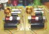
Pair of E'Wave crossovers built by Wiredbecker and the Zilchster using JackLab printed circuit boards made as illustrated in Jackgiff's "Etch yer own" tutorial.

http://www.audiokarma.org/forums/showthread.php?t=191068

Since we're still in prototype mode here ourselves, we added input binding posts in the spare area on the boards provided for an additional capacitor not used with EconoWave. Caps and air-core inductor are mounted with 3M double-side foam tape from the local ACE hardware store:

attachment.php

Tip: Always mount components with the values printed on them facing up so you can read what they are later.... :thmbsp:
 

Attachments

  • JackLab XOs.jpg
    JackLab XOs.jpg
    58.9 KB · Views: 287
Pair of E'Wave crossovers built by Wiredbecker and the Zilchster using JackLab printed circuit boards made as illustrated in Jackgiff's "Etch yer own" tutorial.

http://www.audiokarma.org/forums/showthread.php?t=191068

Since we're still in prototype mode here ourselves, we added input binding posts in the spare area on the boards provided for an additional capacitor not used with EconoWave. Caps and air-core inductor are mounted with 3M double-side foam tape from the local ACE hardware store:

attachment.php

Tip: Always mount components with the values printed on them facing up so you can read what they are later.... :thmbsp:


Very, very slick. I cant wait to make my crossovers look as good as those do.
Nice work, very impressive to say the least:thmbsp:

Russellc
 
My altec 414s are 99db efficient. How much db do I need to "throw away?"

We ran ANDYMAN's Altec woofer's from the Valencia's using the higher then 95DB
xover of Jacks and felt we needed a hair more top end with the L-Pad all the way
up, I would probably build that version with no L-Pad and tweak as need be. :dunno:
 
Pair of E'Wave crossovers built by Wiredbecker and the Zilchster using JackLab printed circuit boards made as illustrated in Jackgiff's "Etch yer own" tutorial.

Since we're still in prototype mode here ourselves, we added input binding posts in the spare area on the boards provided for an additional capacitor not used with EconoWave. Caps and air-core inductor are mounted with 3M double-side foam tape from the local ACE hardware store:

Tip: Always mount components with the values printed on them facing up so you can read what they are later.... :thmbsp:

Those look very professional, I even like the wire choice/color, :thmbsp:
 
Hi Zilch

What is the sensitivity of the Selenium driver on the E'Waveguide?

I get it.

felt we needed a hair more top end with the L-Pad all the way
up,
Kegger
That in essence was my question. I felt the top end can go up a little higher. I am not questioning the design. It may be my personal preference. So, If I were to leave the L Pad in, I would need to add more db by 3 or so? What does that mean in relation to R1 and R2? I am looking at an online calculator. And it says R1 is 4.7ohm and R2 is 38.7ohm. :scratch2:

Thanks guys for your help.

MrT
 
Yah it's not a design flaw in the top end schematic, it's just how much can be squeezed
out of the selenium driver and still have good HF compensation, I believe it's determined
in the past that 98 to 99db is the upper limits of this driver/horn compaired to a woofer.

With no L-Pad at all you just may get a hair more and be right where you want to be at.

You could try decreasing the series resistors by 1 or 2 ohms and upping the paralell ones
by the same amount to see if it gets you there, then tweeking the paralell cap if need be.

That's about the best your going to do with using this selenium on this particular horn, as
this is a pretty shallow horn so will not increase sensitivity as much as some deeper horns.
(Plus it's being compensated to try an flatten the response for good HIFI)
 
You could try decreasing the series resistors by 1 or 2 ohms and upping the paralell ones
by the same amount to see if it gets you there, then tweeking the paralell cap if need be.

Thanks for the reply. This may be MrT's another dummas question. :D But what if I take out R1 and R2 all together? Is that a :nono:?

Thanks
 
A whole nother ball of wax, and not one we could really design without having your setup.

But you could do some frequency shaping on the upper part of your woofer knocking down
some of those upper frequencies which essentially gives you more bass an would give you
less output making the mate to the HF frequency drivers sensitivity more achievable. :)
 
It would be great to go through the crossover you guys are using and provide a chart of R1/R2 values. If I have some time, I'll try to get around to doing that. You've already made two versions of the crossover, so your chart now includes two value pairs. Maybe now would be a good time to add a few to the list.

Don't be confused, 'cause your crossovers use different values than mine. But again, the topology is the same and the intended results are the same. They're pretty much interchangable crossovers. So you might look at the chart of values I have for the Pi crossover:

If you use my crossover, the chart shows the values of R1 and R2 required for various amounts of attenuation from 6dB to 20dB. I'm not advocating you use my crossover, although the results should be the same. But I am suggesting that you might want to add some additional chart entries. I had the same situation you have here - A desire to make my crossover useful with various woofers. So I made a chart for reference, to allow for flexibility just like you guys need here.

The values must be selected with Spice or with careful measurements. It really is not enough to scale the R1/R2 values. You can move them an ohm or two, but if you need to change much more than that, it really helps to have some visibility, the kind of visibility only Spice or measurement equipment can provide. It is easy, almost expected, that to blindly change R1/R2 values can modify the shape of the curve, perhaps causing an unwanted dip or peak in response.

If you look over the chart of values I use in my crossover, you can see the progression of values that result in the right response. I would expect the same kind of ratios would be useful in your crossover.

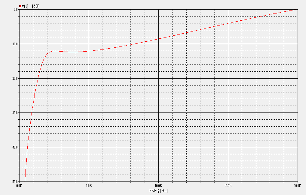
The thing is this: There is a balance that must be struck with the values of R1 and R2. If you increase R1, you tend to increase attenuation. If you increase R2, you tend to reduce attenuation, particularly near the crossover frequency. If R2 is too large, a peak forms near the crossover frequency. If R2 is too small, then the octave or so around crossover is too low. So R1 and R2 must be chosen that provide the desired attenuation and provide this transfer shape:

Top_Octave_Compensation.gif
 
Back
Top Bottom