

You are using an out of date browser. It may not display this or other websites correctly.
You should upgrade or use an alternative browser.
You should upgrade or use an alternative browser.
Zilch's AK Design Collaborative - Econowave Speaker
- Thread starter Zilch
- Start date

The limiting factor in E'Wave is the Seleniums, actually; check the data sheet for their minimum recommended crossover frequency. Jack was able to have the system cross a bit lower by using a higher frequency highpass as part of the compensation, but still avoiding the resonance peak.Let's say that one wanted to use something closer to 900-1200hz as a crossover point, is there a JBL PT wave guide that would be a good match? I'm evaluating some options and this product group is a bit unfamiliar to me.
BMS on the same waveguide easily plays down to 1.0 - 1.2 kHz.
Using the 1.5" throat version and a large-format (4" diaphragm) JBL driver, I have been able to play them to surprisingly low frequencies, ~725 Hz, experimentally.
http://audioheritage.org/vbulletin/showthread.php?p=204976#post204976
Geddes teaches us that cutoff in the traditional sense is not a concept applicable to waveguides, but with one this small, there's still likely to be pattern control issues down that low. I have not run the polars to evaluate.
Others far more competent than myself are now working with similar combinations on LHF, so we may see some more information developed in the future over there:
http://audioheritage.org/vbulletin/showthread.php?p=215693#post215693
The 12" square format versions play a bit lower, but I haven't done much work with them other than cursory measurements. RobH is your authority on those, and he has stymied Geddes with them on another forum, well enough so as to elicit a concession that waveguides are not an absolute, rather, a continuum; there are more "waveguidey" waveguides, and also lesser ones, apparently....


dnewma04
The Healer
Interesting. Thanks for the link. I wouldn't be keen on using a 1.5" throat because of the limitations it places on the drivers unless some 2435s became available for very cheap. Even then, there are a number of drivers I'd rather have.
The Everest mid horn is somewhat interesting, but I dont know much about it, just heard it and was impressed.
The Everest mid horn is somewhat interesting, but I dont know much about it, just heard it and was impressed.
BMS 4555 is 1.5"; several of us are running them on the PTs. Wiredbecker is building his C36s with those right now. :yes:Interesting. Thanks for the link. I wouldn't be keen on using a 1.5" throat because of the limitations it places on the drivers unless some 2435s became available for very cheap. Even then, there are a number of drivers I'd rather have.
Everest I (the big controlled directivity one,) or Everest II?The Everest mid horn is somewhat interesting, but I dont know much about it, just heard it and was impressed.
dnewma04
The Healer
BMS 4555 is 1.5"; several of us are running them on the PTs. Wiredbecker is building his C36s with them right now. :yes:
Sorry, I meant K2, not Everest.
H9800, I think.
The big CD in the original everest would be slick, though.
I got yelled at for messing with H9800:Sorry, I meant K2, not Everest.
H9800, I think.
The big CD in the original everest would be slick, though.
http://audiokarma.org/forums/showthread.php?p=1759674#post1759674
Here's the wider H4338:
http://audiokarma.org/forums/showthread.php?p=1745584#post1745584
Not OT, BTW, rather, followup to my earlier statement:
There are other larger and more expensive modern horns and waveguides that will easily stomp these vintage Altecs, performance-wise; I've shown a couple of them in other threads here on AK.
H9800 has been scanned, and several LHF members have made clones, including AKer John W:You have the geometry for that horn, Z?
http://audioheritage.org/vbulletin/showthread.php?t=14933
H4338 has not been scanned, best I know....


Russellc
Addicted Member
The limiting factor in E'Wave is the Seleniums, actually; check their data sheet for their minimum recommended crossover frequency. Jack was able to have the system cross a bit lower by using a higher frequency highpass as part of the compensation, but still avoiding the resonance peak.
BMS on the same waveguide easily plays down to 1.0 - 1.2 kHz.
Using the 1.5" throat version and a large-format (4" diaphragm) JBL driver, I have been able to play them to surprisingly low frequencies, ~725 Hz, experimentally.
http://audioheritage.org/vbulletin/showthread.php?p=204976#post204976
Geddes teaches us that cutoff in the traditional sense is not a concept applicable to waveguides, but with one this small, there's still likely to be pattern control issues down that low. I have not run the polars to evaluate.
Others far more competent than myself are now working with similar combinations on LHF, so we may see some more information developed in the future over there:
http://audioheritage.org/vbulletin/showthread.php?p=215693#post215693
The 12" square format versions play a bit lower, but I haven't done much work with them other than cursory measurements. RobH is your authority on those, and he has puzzled Geddes with them on another forum, well enough so as to elicit a concession that waveguides are not an absolute, rather, a continuum; there are more "waveguidey" waveguides, and also lesser ones, apparently....
I used them with 2425H on top of my A7s crossed at 800 and it sounded surprisingly good but this may be pushing it.
Russellc

Wayne Parham
Active Member
16 ohm compression drivers
The use of 16 ohm compression drivers on a CD horn or waveguide having a crossover designed for an 8 ohm driver is a non-trivial problem. The reason is the crossover provides three things, frequency splitting, SPL matching via padding and top-octave compensation by removing the padding at 6dB/octave above a certain point. So there are a few things to juggle to get the transfer function right. There is more to it than just the value of the high-pass splitter filter components, and you don't necessarily scale the values like you might in a simpler crossover.
To review, the signal you want presented to the tweeter is the conjugate of its power response. The way to get that is to provide 6dB/octave augmentation, starting at the mass rolloff frequency of the compression driver. Below that frequency, response should be flat, simply attenuated to match the level of the midwoofer.
The best way I've found to provide that curve is to allow a small amount of peaking around the crossover point, just enough to add together with a diagonal line of 6dB/octave augmentation to provide an overall curve that starts off flat, then ramps up top-octave compensation where mass rolloff begins. The augmentation is provided by gradually removing the padding that is required to match the SPL of the midwoofer with the tweeter.
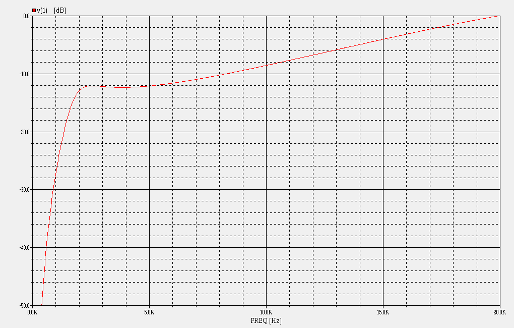
For those of you familiar with the use of CD horns, this concept is not new. The thing is, once you've worked out the component values for 8 ohm drivers, you can't necessarily scale them for use with 16 ohm drivers. There is a specific load and damping amount that you want, and it is set by the value shown as R2 in my crossovers (see schematic for reference), and this value is more important to the "core" high-pass splitter filter than the compression driver impedance. The values of R1 and C1 set the attenuation and, to a lesser degree, interact with the compression driver and with R2 to set all the other variables. You really have to work out these values as a system, not individually and not by scaling. The wrong values can cause too much peaking near the crossover point, or too little.
When I first started making crossovers like these, I worked everything out for 8 ohm drivers. I really expected that to use 16 ohm drivers, there would need to be more changes required of the core splitter filter, but found out this was not the case. They are the same, since the main load is provided by resistor R2. I found that the thing to do was to modify the R1/R2/C1 values to present the same load to the splitter filter, but to also modify the voltage division for the higher impedance compression driver. It has lower voltage sensitivity and higher impedance, so the R1/R2/C1 values should be set accordingly. It can be done with Spice, or empirically with build/measure/test cycles.
After all the analysis was done, I found that a 16 ohm compression driver swap really only required the value of R1 to be changed from 16 ohms to 50 ohms, and C1 from 0.47uF to 0.33uF.
The use of 16 ohm compression drivers on a CD horn or waveguide having a crossover designed for an 8 ohm driver is a non-trivial problem. The reason is the crossover provides three things, frequency splitting, SPL matching via padding and top-octave compensation by removing the padding at 6dB/octave above a certain point. So there are a few things to juggle to get the transfer function right. There is more to it than just the value of the high-pass splitter filter components, and you don't necessarily scale the values like you might in a simpler crossover.
To review, the signal you want presented to the tweeter is the conjugate of its power response. The way to get that is to provide 6dB/octave augmentation, starting at the mass rolloff frequency of the compression driver. Below that frequency, response should be flat, simply attenuated to match the level of the midwoofer.
The best way I've found to provide that curve is to allow a small amount of peaking around the crossover point, just enough to add together with a diagonal line of 6dB/octave augmentation to provide an overall curve that starts off flat, then ramps up top-octave compensation where mass rolloff begins. The augmentation is provided by gradually removing the padding that is required to match the SPL of the midwoofer with the tweeter.
For those of you familiar with the use of CD horns, this concept is not new. The thing is, once you've worked out the component values for 8 ohm drivers, you can't necessarily scale them for use with 16 ohm drivers. There is a specific load and damping amount that you want, and it is set by the value shown as R2 in my crossovers (see schematic for reference), and this value is more important to the "core" high-pass splitter filter than the compression driver impedance. The values of R1 and C1 set the attenuation and, to a lesser degree, interact with the compression driver and with R2 to set all the other variables. You really have to work out these values as a system, not individually and not by scaling. The wrong values can cause too much peaking near the crossover point, or too little.
When I first started making crossovers like these, I worked everything out for 8 ohm drivers. I really expected that to use 16 ohm drivers, there would need to be more changes required of the core splitter filter, but found out this was not the case. They are the same, since the main load is provided by resistor R2. I found that the thing to do was to modify the R1/R2/C1 values to present the same load to the splitter filter, but to also modify the voltage division for the higher impedance compression driver. It has lower voltage sensitivity and higher impedance, so the R1/R2/C1 values should be set accordingly. It can be done with Spice, or empirically with build/measure/test cycles.
After all the analysis was done, I found that a 16 ohm compression driver swap really only required the value of R1 to be changed from 16 ohms to 50 ohms, and C1 from 0.47uF to 0.33uF.

Bauhausler
Rational Subjectivist
Hey All!
Kegger called me the other day to make sure I was still breathing and to ask me to drop in for a minute. I haven't fallen off the face of the earth. I was waiting for parts for the EconoWAdvents. Then I got overwhelmed with work, 7 days a week, often until way past midnight. No time to experiment with speakers, and no time for AK.
I'm still around, and I'm still going to do my speakers, just maybe not this month.
I'll keep you posted.
Gotta go!
Kegger called me the other day to make sure I was still breathing and to ask me to drop in for a minute. I haven't fallen off the face of the earth. I was waiting for parts for the EconoWAdvents. Then I got overwhelmed with work, 7 days a week, often until way past midnight. No time to experiment with speakers, and no time for AK.
I'm still around, and I'm still going to do my speakers, just maybe not this month.
I'll keep you posted.
Gotta go!

Bauhausler
Rational Subjectivist
Glad to hear from you!!
Let us know how those UAs work out. That may be just about the most common setup for folks to convert :yes:
Thanks, Andy. That's why I picked these instead of my first choice the LE10A in L77 cabinet. Advents are pretty thick on the ground. (you own what, like 4 1/2 pairs?) I like everything about them except the tweeter, which is the most fragile part anyway. It seemed like a project that would have value to a number of people. When done, I'd be willing to ship them, paying round-trip cost, for Real Instrumented Testing so the Xovr could be fine tuned into a final version. For a project that was likely to be duplicated by other people, that seemed worth doing.


skywave-rider
Slumming in Akihabara
...I really expected that to use 16 ohm drivers, there would need to be more changes required of the core splitter filter, but found out this was not the case....
Thank you Wayne.
I intend to give your circuit a go with BMS drivers after I get my new woofers. Perhaps Mr. T, with 16 Ohm HF, will go L-pad-less and take your approach. I would assume from what you said, he could do so by keeping the core splitter as specified for Econowave, and use the 16 ohm values in r1/r2/c1 in your schematic to get attenuation and augmentation. Sound OK?
After posting, I saw Mr.T has just posted finishing his crossovers, but I would still like to know if you think what I said above is acceptable.