You are using an out of date browser. It may not display this or other websites correctly.
You should upgrade or use an alternative browser.
You should upgrade or use an alternative browser.
Zilch's AK Design Collaborative - Econowave Speaker
- Thread starter Zilch
- Start date

mrTT
Active Member
mrT getting confused.
Wayne. C1 I thought is 4.7f. So should I change that to 3.3uf? Changing R1 to 50 is not a big problem.
Thanks
After all the analysis was done, I found that a 16 ohm compression driver swap really only required the value of R1 to be changed from 16 ohms to 50 ohms, and C1 from 0.47uF to 0.33uF.
Wayne. C1 I thought is 4.7f. So should I change that to 3.3uf? Changing R1 to 50 is not a big problem.
Thanks
Attachments


skywave-rider
Slumming in Akihabara
T,
Wayne is talking about his own schematic, not Econowave. If you click the link in his post you'll see. Since you already built up the x-overs, try them out as they are.
Wayne is talking about his own schematic, not Econowave. If you click the link in his post you'll see. Since you already built up the x-overs, try them out as they are.


Bauhausler
Rational Subjectivist
Hey Bauhausler, you have to come over again and listen to my ESS EWGs. With the updated crossover and the switch around in amps, they sound fantastic. Cheers.
Kegger told me they sounded great. Did I leave anything necessary out of that kit of crossover parts? Aside from the labor.
I'll get back to the EWaves a lot faster if someone knows what would make only one channel of an Ampzilla generate exactly .25VDC of output stage offset for every 1 VRMS of output signal. I've banged on this problem for a total of 30 hours over 2 1/2 days and I'm right back where I started, but with a large heap of nearly new 'takeoff' transistors, diodes and resistors. The other channel is identical terms of every visual, electrical and component factor except for this very exact, repeatable and completely aberrant DC behavior. I'm ready to piss on B+ if that would help.
I hate direct coupled SS amps with a score of active devices in 20 square inches. I love tube amps with a total of 3 active parts and voltages, currents and impedances large enough to measure.

I did end up changing a few things. I am bi amping so I went to the high eff woofer crossover so I got more out of my horns. Keg made the suggestion that I put in a 6.2uf across the woof post instead of the 12uf the plans call for and that brought up the lower vocal range on the woofs. The biggest difference thou is taking the Adcom SS amp out and using my 300B amp for the woofs and the Decware Zen amp for the horns. These things sound GREAT. I listened for three hours today and totally lost track of time. I was thinking of bringing them to the next SMAC but then realized I was going to be in Hunting camp that weekend. Maybe you can stop by for lunch next week. Cheers.

jackgiff
Well-Known Member
So, I am not changing a Jack. Right Jack? I worked 25 hours shift yesterday. And I just finished putting my crossover together. So, U need to give me some straight talk here. :drool: Otherwise, MrT gets violent.
Waynes crossover is different than the EconoWave crossover. It uses third order hi pass, while the EconoWave uses second order. Don't be confused by Waynes description of changes done to his crossover. Even his component designations are different. Build it with the values I gave you to start. And by the way, since the crossover and HF drivers are both 16 Ohms, it goes without saying that you should use 16 Ohm L-Pads as well.

Russellc
Addicted Member
Ok I got my crossover finished. D220tis are here. And the waveguides are coming tomorrow.
Exciting!
Yes it is! Quite a treat to get fired up, a real rewarding project. Post lots of pics!
Cheers,
Russellc
Russellc
Addicted Member
Update on the 2235H in my JBL 4647 boxes. After a little break in, they are sounding fantastic. A little more play and the CC crossover is going in for a trial run. Once that is done, the crossover is changing to the low pass of 4430 as suggested by Zilch. After that a possible Non econo high frequency unit, like BMS, JBL or B&C. At that point it will really not be econowave anymore and will have a linked thread of its own. Then, the 2213H econowaves will be built and the cc crossover to them, if it proves to be an improvement worth following.
Russellc
Russellc
 :thmbsp:
mrTT
Active Member
MrT is happy now
Thanks everyone
Careful, now. E'Wave highpass departs from Wayne's design with a higher frequency and lower "Q" to compensate for the Selenium's excess output in the 2 kHz region. Use the values Jack specified for 16 Ohms....
Got it!Wayne is talking about his own schematic, not Econowave. If you click the link in his post you'll see. Since you already built up the x-overs, try them out as they are.
I got it. That's the way I made it in the first place.Waynes crossover is different than the EconoWave crossover. It uses third order hi pass, while the EconoWave uses second order. Don't be confused by Waynes description of changes done to his crossover. Even his component designations are different. Build it with the values I gave you to start. And by the way, since the crossover and HF drivers are both 16 Ohms, it goes without saying that you should use 16 Ohm L-Pads as well.
I really am looking forward to it. I post my first picture at #2062 . A home made crossover. I did not use a board as the one Jack put together. I don't have the means to do it.Yes it is! Quite a treat to get fired up, a real rewarding project. Post lots of pics!
Thanks everyone

Wayne Parham
Active Member
The main point I wanted to make is going to a 16 ohm driver from an 8 ohm driver doesn't necessarily mean you should scale crossover component values as one might expect.
I suggest working it out with Spice. When I did that a few years back, I found that the R1/R2/C1 network was all that should be changed, and in fact, only R1 and C1 was necessary. R2 stayed the same.
The issue is the loading of the splitter HP filter, the "core" of the crossover. Crossovers greater than first-order are very prone to peaking if the load impedance is increased. This is because the crossover acts like a tank circuit - the load impedance damps the filter, setting the Q of its resonance. As the load impedance is increased, the Q of the filter increases too.
This property of higher-order filters is used to our advantage in CD compensation. Without it, you couldn't make the initial flat shelf before starting 6dB/octave augmentation. Because of that, you can't make a filter that is the conjugate of CD power response using a core splitter that's first-order, it has to be second-order, third-order, or greater. This is fine, because higher-orders are good for other reasons too.
When you load the core filter with R1/R2/C1 as in my crossover, or with a similar network as in yours, this network sets the load. The compression driver is in shunt with that load, but is partially isolated with padding resistors. It's a higher impedance leg that doesn't drop the load impedance "seen" by the core filter very much. Consequently, it doesn't affect the crossover frequency or Q very much.
I don't know what work you guys have done to model your crossovers in Spice, or to measure physical models. I can see you've done some measurements, but wasn't sure how much experience you had with that, especially in regards to the value shift when going to a 16 ohm compression driver. I saw some discussion of scaling values like what is normally done on simpler networks, doubling inductance and halving capacitance. I wanted to point out that isn't the way to go, and to suggest instead that Spice models be used to find the values you needed. For illustration, I showed my crossovers because the work has been done there and because your crossovers are very similar. Their basic topology is the same.
One last thing. I've mentioned Spice a few times here. It was the main tool I used to develop my crossover many years ago. I would strongly suggest downloading and using it when contemplating changes to your crossovers too. You can download the models for my crossover and modify them for your values, if you wish. Spice is an excellent tool for this kind of thing.
You can even import your Spice models into Keith Larson's WTPro system, which will make a digital crossover for acoustic testing. This lets you change crossover component values by editing a Spice description file. You can then make acoustic measurements of a physical loudspeaker. The cool thing that buys you is the ability to do polar measurements and set your null angles on the fly. You can easily modify crossover values between each measurement, trying new configurations in seconds. When you're trying to optimize a speaker not only in axial response but also off-axial, this kind of test/modify/re-test cycle is really great. It is probably the best rapid prototyping tool I've ever used, extremely helpful for optimizing the crossover.
I suggest working it out with Spice. When I did that a few years back, I found that the R1/R2/C1 network was all that should be changed, and in fact, only R1 and C1 was necessary. R2 stayed the same.
The issue is the loading of the splitter HP filter, the "core" of the crossover. Crossovers greater than first-order are very prone to peaking if the load impedance is increased. This is because the crossover acts like a tank circuit - the load impedance damps the filter, setting the Q of its resonance. As the load impedance is increased, the Q of the filter increases too.
This property of higher-order filters is used to our advantage in CD compensation. Without it, you couldn't make the initial flat shelf before starting 6dB/octave augmentation. Because of that, you can't make a filter that is the conjugate of CD power response using a core splitter that's first-order, it has to be second-order, third-order, or greater. This is fine, because higher-orders are good for other reasons too.
When you load the core filter with R1/R2/C1 as in my crossover, or with a similar network as in yours, this network sets the load. The compression driver is in shunt with that load, but is partially isolated with padding resistors. It's a higher impedance leg that doesn't drop the load impedance "seen" by the core filter very much. Consequently, it doesn't affect the crossover frequency or Q very much.
I don't know what work you guys have done to model your crossovers in Spice, or to measure physical models. I can see you've done some measurements, but wasn't sure how much experience you had with that, especially in regards to the value shift when going to a 16 ohm compression driver. I saw some discussion of scaling values like what is normally done on simpler networks, doubling inductance and halving capacitance. I wanted to point out that isn't the way to go, and to suggest instead that Spice models be used to find the values you needed. For illustration, I showed my crossovers because the work has been done there and because your crossovers are very similar. Their basic topology is the same.
One last thing. I've mentioned Spice a few times here. It was the main tool I used to develop my crossover many years ago. I would strongly suggest downloading and using it when contemplating changes to your crossovers too. You can download the models for my crossover and modify them for your values, if you wish. Spice is an excellent tool for this kind of thing.
You can even import your Spice models into Keith Larson's WTPro system, which will make a digital crossover for acoustic testing. This lets you change crossover component values by editing a Spice description file. You can then make acoustic measurements of a physical loudspeaker. The cool thing that buys you is the ability to do polar measurements and set your null angles on the fly. You can easily modify crossover values between each measurement, trying new configurations in seconds. When you're trying to optimize a speaker not only in axial response but also off-axial, this kind of test/modify/re-test cycle is really great. It is probably the best rapid prototyping tool I've ever used, extremely helpful for optimizing the crossover.
jackgiff
Well-Known Member
When you load the core filter with R1/R2/C1 as in my crossover, or with a similar network as in yours, this network sets the load. The compression driver is in shunt with that load, but is partially isolated with padding resistors. It's a higher impedance leg that doesn't drop the load impedance "seen" by the core filter very much. Consequently, it doesn't affect the crossover frequency or Q very much.
Wayne, We really appreciate your sharing your wisdom with us, and bringing us along. When we were first asked about using 16 Ohm HF drivers it seemed to me that since we have an L-Pad in the circuit to adjust for different woofers, that maybe it would be best to keep everything configured for 8 Ohms or for 16 Ohms. The L-Pad is supposed to keep the impedance constant as it is varied. But should we use an 8 Ohm or 16 Ohm? And how much would using the "wrong" one affect the performance?
I ran a production house for 26 years, and gave it to my sons. I know about keeping costs down by using "stock" parts where possible. Since you probably use way more 8 Ohm drivers, it would be best to figure out a way to use the same crossover parts as the 8 Ohms whenever you do a special project with 16 Ohm drivers, since those parts are probably already on hand. But if building only one pair 16 Ohm speakers, and having no parts on hand, doesn't it make more sense to buy the correct parts, instead of using something that "doesn't change much?" That was my rationale for using the 16 Ohm values.
Thanks for the references to using Spice, too. Zilch has Spice, and uses it considerably, but since I am retired, and speakers is just a hobby, I haven't got infatuated with using it yet. Maybe the time will come for that.
Wayne Parham
Active Member
The good news is it probably doesn't matter much whether you use an 8 ohm driver or a 16 ohm driver if you use an 8 ohm circuit. The R1/R2/C1 network (or whatever nomenclature you use) will dominate.
I think it would be worthwhile to model this in Spice though. It's easy, and it shows you what's going on inside your circuit. The download is free, comes with the executable and models of my crossovers which you can easily modify to your needs.
I think it would be worthwhile to model this in Spice though. It's easy, and it shows you what's going on inside your circuit. The download is free, comes with the executable and models of my crossovers which you can easily modify to your needs.

I think it would be worthwhile to model this in Spice though.
http://audiokarma.org/forums/showthread.php?p=2142479#post2142479
Wayne Parham
Active Member
Very good, Zilch. I remember seeing that post a few months back.
So since you have the Spice models, maybe change Le and Re for values appropriate to a 16 ohm driver and see what happens? I suggest using values Le = 0.2mH and Re = 12 ohms. That will tell you how most 16 ohm compression drivers will act in your crossover.
So since you have the Spice models, maybe change Le and Re for values appropriate to a 16 ohm driver and see what happens? I suggest using values Le = 0.2mH and Re = 12 ohms. That will tell you how most 16 ohm compression drivers will act in your crossover.

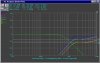
My sims are merely 8-Ohm resistive loads, not actual driver models. If I bump them (there are two versions with different attenuations) to nominal 16 Ohms, Spice says, "Not that simple." Yellow and Cyan are the "standard" E'Wave filters:So since you have the Spice models, maybe change Le and Re for values appropriate to a 16 ohm driver and see what happens?