• The move to the new server is done. There are some software and database maintenance updates in process. This has us passing the hat around to help out. We appreciate any donations. Seriously, even a dollar helps. The payment page may be found here - https://www.audiokarma.org/support.html

Zilch's AK Design Collaborative - Econowave Speaker

Well I can't remember the name of the company. :D I only worked there for three weeks and then had an opportunity to go sailing to Catalina Island for two weeks and immediately quit. There were some scary dudes working there. I remember one guy was out on bail for murder. No kidding. :yikes: I stayed clear of that gang banger. :yes:

He's pulling your leg, murder i snt bondable. Sheese, even O'jay couldnt bail out, I'm sure that smuck couldnt!:D I represent lots of "big talkers" they think that stuff is a badge of honor or something.

russellc
 
I hear yu Duff, I've got a pair of 570's staring at me now dammit..:scratch2:

No tweets in these ones, personally I like a good sounding dome tweet
and don't feel that a waveguide and compression driver is warrented in
an ineficent speaker like most ADS are, and personally I wouldn't find it
to be an upgrade either, even with all the advanteges it provides....:whip:

Again it comes down to ones thoughts on the subject of matching the
sensitivity and how they feel certain components mesh with each other
then ultimatly the subjective sound of each speaker system as a whole.

I have no problem with someone else doing it, just not sure I would and
I like the speakers as they are and feel they perform rather well to boot.

Again this is not to try an derail anyone from doing it, and I will be extremly
interested if someone does do it plus feel they would probably sound great!
(Just voicing my oppinion on the subject is all)

There are certainly better components out there and better performing then
the ADS speakers, but they are one of the "vintage" types I happen to like. :)
Good points and I have no idea how much HF compensation would be needed to match the L620 10" woof. I bet there are some L620's out there with fried tweets, especialy older ones without the fuses, that would be nice candidates. They have nice looking solidly constructed cabinets that might be worth the effort, even with different woofers. The baffles in the L620 are not removeable but their big flat face just scream "give me a waveguide". :thmbsp:

And I would not destroy a pair of L570's to add waveguides, only the L620. :yes:
 
Hey does this qualify for the Econowave projects??? I only ran it for a week or two while waiting for PRs for my ESS Ewaves. I did not use the tweet, just the ewave xover, WG, 210 driver and the Jensen Imperial for woofs.

IMG_3257.jpg
 
Good points and I have no idea how much HF compensation would be needed to match the L620 10" woof.

I have a line on two of those woofers... :naughty: Will give them a shot in the L56 cabs.

If they prove to need too much 'cipherin' I'll stick with the original woofs, which are growing on me...

I've been sidelined on tweaking due to (besides life-in-general) packing up a monster SX-1010 for shipping.:gigglemad
 
Just got off the phone with Dave at JBL. It seems we have now run them out of stock on the 6x6" waveguides. Next production scheduled for April.

He said he will try to "find" a few for enthusiastic project builders. Stay tuned... :boring:
 
Thats cool because I just spoke to him this morning and they got the 6x12 back in stock, Mine are due to be delivered thursday so ill be able too FINALLY hear what these are capable of. Everything else is done, all I need to do is screw the drivers on to the wageguides, connect the wires, and screw them into cabinets. The anticipation is killin me. I think Ill order another set just to be safe.
 
Just got off the phone with Dave at JBL. It seems we have now run them out of stock on the 6x6" waveguides. Next production scheduled for April.

He said he will try to "find" a few for enthusiastic project builders. Stay tuned... :boring:
That usually means there may be a few in production inventory he can "borrow" outside of the standard materials control procedure there. It does require additional effort, but both Dave and Carla are friends of E'Wave, and willing accomplices.... ;)
 
That's what he intimated. I still think it's hilarious that they're selling bazillions of waveguides, but very few drivers. There's gotta be an executive somewhere scratching his head over the numbers. :headscrat
 
I don't know. They sell the waveguide for $9.90 and the drivers go for $275-$1000. Doesn't really take a rocket surgeon to figure it out. Of course we're talking executives so... ;)
 
Going down that road causes one to wonder about margins... :smoke:

Those waveguides gotta be cheap to make! I'm talking pennies, here. Injection molding is cheap, cheap, cheap.
 
Trying to qualify 8 inch square waveguide.

Since the 6 inch square waveguide just substitutes for the 12 X 6 inch version with no differences in compensation, and there is some interest in the 8 inch square version, it seemed like it was time to fully test the 8 incher. I looked at it some time ago, and knew it wouldn't be a direct substitute, but needed some more upper end compensation.

But after playing with it most of this afternoon, it doesn't seem likely to be an Econo fix to make it as flat as the other two (three actually, since the Pyle waveguide is equivalent to the 12 X 6).

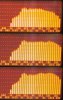
The goal in selecting the value of the HF compensation capacitor is too just compensate the upper octaves while leaving the mid ones flat. Adding any more capacitance to the 1.5 uf capacitor in the LE14A crossover starts to lift the mid ranges as well as the upper. This is shown in the progression of FR's taken while testing. I feel the values selected for C3 in the two crossover schematics used in the EconoWave are pretty much approaching their peak usable values.

I had built crossovers for my rear channels already so used one of them for this test. It is the crossover for the LE14A. The first panorama images shows the uncompensated (no C3) FR at the top, the standard value of 1.5 uf for C3 in the middle, and 2.5 uf for C3 on the bottom. The only real difference in the two compensated FR's is that the mid ranges are raised in the bottom one. The drop in the last 4 or 5 bands of both is still roughly 7 dB.

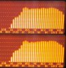
I felt that splitting the resistor R1's value into several resistors whose sum is the total value of R1 might give me an opportunity to sum up the effects of several sets of compensating capacitors. (Harkening back to my Data Conversion days I suppose) I used four each 4 Ohm resistors in place of the 16 Ohm. Capacitor values were tried from 1 uf to 2 uf. It didn't matter whether the largest cap or the smallest was connected to the driver, while the remaining ones were distributed along the divider junctions. The second panorama shows the results of two tests with the largest cap on the driver end, and the other with the largest cap on the crossover end. It really didn't matter, and both tests showed essentially the same resaults as simply making C3 bigger. No real fix. The last picture shows the multiple resistors and capacitors being jumpered to the selected locations with jumpers.

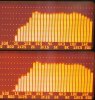
The last panorama shows the normally compensated crossover on top, and the bottom is with a C3 value of 1 uf. The 1 uf is almost enough compensation, but the 1.5 uf just seems ideal.

There are obviously ways to fix the FR so that it will be flat, but it won't be Econo. One way is to add active equalization to the top end, but that takes frequency sensitive gain. Another is to pad down the range from 1.6 KHz to about 15 KHz, but that takes some high priced parts, and wastes response needed by the HF compensation scheme.

So unless someone else has another bright idea, maybe that is as good as it will get with the 8 inch version. It's curves must be responsible for the difference in response on the top bands.

Do we say it is usable as is? It really sounds good, and will be used in my rear channels as is. After all, even the venerable JBL 4430 isn't flat from 16 to 20 KHz.
 

Attachments

  • Panorama1.jpg
    Panorama1.jpg
    95.9 KB · Views: 29
  • Panorama3.jpg
    Panorama3.jpg
    97.6 KB · Views: 22
  • Panorama2.jpg
    Panorama2.jpg
    98.5 KB · Views: 30
  • 8InchSquareTest.jpg
    8InchSquareTest.jpg
    68.4 KB · Views: 46
What's the thought on passives?

Asking because I am contemplating what to do with the S99 cabs, I'm thinking of using
some other old cabs, and attaching them to the bottom of the S99, with a chamber in
connecting the 2 together and since they had a woof before it would be easy to stick
a set of passives in each one. I have some passives here, one set is squicle like LE14
and pretty close to the same size, there nice looking cast baskets from some Sansuis.

I've never attempted to build with passives, I know you add or remove mass to tune
them and I assume I could use WT3 to accomplish this, any thoughts on the subject?

Any benefits or things not to like about passives?
 
So unless someone else has another bright idea, maybe that is as good as it will get with the 8 inch version. It's curves must be responsible for the difference in response on the top bands.

Do we say it is usable as is? It really sounds good, and will be used in my rear channels as is. After all, even the venerable JBL 4430 isn't flat from 16 to 20 KHz.
In my study of Wayne's chart, I determined that 1.5 uF was the max usable cap value, and even with that, we're giving up a bit of comp at 20 kHz, as the rollover frequency begins below there with higher values.

I'm using the D220Ti on the 8" waveguide in my large Advents, and the comp from my earlier KLH-17 project using a different waveguide was plug-'n'-play:

http://audiokarma.org/forums/showthread.php?p=2434268#post2434268

Not terribly smooth in the highest octave, but not rolled-off there, either. There's also unit-to-unit variability in the drivers that needs accounting for.

Given the sensitivity of the Advent woofer(s), this would be more equivalent to your low-efficiency crossover, but if you can verify the highpass here, I'll tweak it up to max, similar to what I did in that earlier study.

The actual built-out crossover is on the next page; I assume we'll have to adjust the lowpass for LE14A, and perhaps the "generic" spec, as well.... :yes:


What's the thought on passives?
They'll work. JBL used a 15" passive with LE14A in L220/2. The problem is where to put it (or them). For my own part, front is best. Port's easier.... :yes:
 
I'm using the D220Ti on the 8" waveguide in my large Advents, and the comp from my earlier KLH-17 project using a different waveguide was plug-'n'-play:

http://audiokarma.org/forums/showthread.php?p=2434268#post2434268

Not terribly smooth in the highest octave, but not rolled-off there, either. There's also unit-to-unit variability in the drivers that needs accounting for.

I realize that there are differences between my using RTA and the MLS measurements that you used for the Advent system. MLS shows much more peaking than the smoothed response of RTA. But it looks to me like there are similarities in the highest octave, nevertheless. Measuring from the top of the large wide positive peak at about 12 KHz on the Advent FR, there seems to be a downward slope, ending about 6 dB down at 20 KHz. The fast upward spike just before the 20 KHz mark may seem to make it read better, but it is quite narrow, isn't it? Is that same 6-7 dB slope not really there? Am I imagining it?

I fail to see how two different waveguides can be "plug and play" at lower SPL's and not be "plug and play" at higher SPL's. That is going to be decided by the geometry of the waveguides curves, isn't it? Was the different waveguide the 18Sound unit?

Given the sensitivity of the Advent woofer(s), this would be more equivalent to your low-efficiency crossover, but if you can verify the highpass here, I'll tweak it up to max, similar to what I did in that earlier study.

The actual built-out crossover is on the next page; I assume we'll have to adjust the lowpass for LE14A, and perhaps the "generic" spec, as well.... :yes:

A 60 Ohm value for the attenuation resistor would throw away roughly 20 dB of the tweeters response. Maybe that would allow for better HF compensation, but don't we want to make the EconoWave use "virtually any woofer" that can play nicely up to 1.6 KHz? I quit playing with the 8 inch square waveguide when it obviously (to me, anyway) couldn't be simply tweaked to match the highest SPL woofers, which seemingly should be the worst case. Even with lower SPL woofers, and bigger values of the attenuation resistor, the compensation capacitor will still tend to raise the mids along with the high end, will it not? Maybe I will play with it some more tomorrow.

I am willing to give the 8 inch square waveguide my blessing, and I plan to use it in a pair of speakers that are in process. It really does sound nice. Maybe it will not be objectionable to Kegger and some of the others who use a foam plug to knock the highs down. Could be that it isn't necessary with this waveguide. Kegger, can you give us a read on that?
 
Gotcha Zilch no doubt porting would be easy.

My thinking was if I want to build a bottom/box for these I've got extra cabs around
that have no drivers so I'm probably going to use them, seems to be less work for me
then I figured the passive could look cool down below (yes on the front) and the hole
where the woofer was would easily be filled with the passive. Seems like it could be a
good use of "real estate".

So just testing the waters here, I am not sure of the benefits or pitfalls that passives
may have to them and any tricks to possibly use when building with them as well here.
(Gotta do some more googling)
 
Hey Jack....

My take on the Foam plug, at least the small amount I use is it did not just knock down
the extreme highs but more so did it smooth out the response of all the high frequencies
from say 6k on up, it almost seemed to hold back the compensation from starting at the
lower frequencies it normally would, it seemed to shelve those back a tad more then the
extreme highs were affected, allmost like correcting an anomaly in the horn maybe?.

You may actually want to try it here and see how it responds for you, my guess is the
more you use the more it affects extreme highs, I experimented with different amounts
or basically size of the plug till I got what I was after on my cheapo test rig equalizer. :)

I could always see a peak at 8K then starting to drop at 16K, when I got the right foam
in there 8K was no longer a peak and the 16K was pretty flat.

I like "air" in my highs, the plug actually made it easier to hear without cranking the L-Pad.:dunno:
Before I used the plugs when I had the L-PAD up enough to get shimmery sparkly highs an
air it would be to hot and sibilant for me, it was tough to balance it just right.

Having said all that, I do not think your measurements look all that bad and probably does
sound rather good, an like you speculate some may prefer it.
 
I fail to see how two different waveguides can be "plug and play" at lower SPL's and not be "plug and play" at higher SPL's. That is going to be decided by the geometry of the waveguides curves, isn't it?
Yes, so long as the HF comp contour is the same, which can be achieved at varying attenuation levels using different component selections as, for example, shown in Wayne's chart. The requisite comp for the 8" waveguide is different from the other PTs.

A 60 Ohm value for the attenuation resistor would throw away roughly 20 dB of the tweeters response.
Yes, but that 20 dB is the sum of the HF comp that was needed to make this waveguide play flat using D220Ti PLUS the additional attenuation necessary for it to mate with the relatively low-efficiency Advent woofer.

I'm asking you to try my Advent highpass on your waveguide and driver to confirm that the comp is correct, independent of the overall attenuation. If it plays flat for you, I'll then go ahead and develop the same compensation with zero attenuation for mating with higher-efficiency woofers.... :thmbsp:
 
I second what Keg said. The foam plugs really smooth out the highs without loss of signal. He made them at my table while we were listening to music and drinking beer.
 
JBL LE15B T/S parameters

Re: 3.3-3.6 ohms
Fs: 24-26hz
Qts: .1633 - .1859
Qes: .1803 - .1950
Qms: 4.172 - 4.763
Le: .58 mH

Vas: measurements to follow.

Based on specs, I"d say it's begging for a big corner horn...
 
Back
Top Bottom