

You are using an out of date browser. It may not display this or other websites correctly.
You should upgrade or use an alternative browser.
You should upgrade or use an alternative browser.
Zilch's AK Design Collaborative - Econowave Speaker
- Thread starter Zilch
- Start date

Russellc
Addicted Member
Still not an official 'waver yet, but I'm one step closer.
Today I went to meet the local JBL reconer (Russellc knows Slice) and he's gonna order up some LE10H kits....
Slice is the JBL reconer I use. They are fantastic, and will do a great job.
Quick too!:yes:
Russellc

Bauhausler
Rational Subjectivist
AR3/5AWAVE Version 3
I'm still listening to the PH612 horns with D210Ti drivers and Kef B110 and AR3a woofers. I've changed around the crossover scheme. I decided to go for a higher crossover point from mid to tweeter. Using a 3-way active xovr I now have the crossover points set at 200 hz and 3khz. The only passive filtering in the system now is the CD compensation for the treble.
This way the B110 is doing the bulk of the important work, handling everything from 200 to 3K. I think the midrange might need some notch filtering on it. The FL6-23 LS3/5A crossover puts in series with teh B110 a parallel combination of 6.2uf, 2.67 mh and 33 Ohms. IIRC, Fc= 1/(2 pi (sqrt(LC)) so the center freq should be 1250 hz. I can hear a little prominence in the mids so maybe I'll try out that notch filter if I can round up the right inductors.
Here's a question about the CD compensation. This consists of 15 Ohms in series, bypassed with .47uf, and 24 - 30 Ohms in parallel. If the crossover point is raised, what effect does this have on the CD compensation? Do the component values have to be changed? My gut says 'no' but I thought I'd ask.
I'm still listening to the PH612 horns with D210Ti drivers and Kef B110 and AR3a woofers. I've changed around the crossover scheme. I decided to go for a higher crossover point from mid to tweeter. Using a 3-way active xovr I now have the crossover points set at 200 hz and 3khz. The only passive filtering in the system now is the CD compensation for the treble.
This way the B110 is doing the bulk of the important work, handling everything from 200 to 3K. I think the midrange might need some notch filtering on it. The FL6-23 LS3/5A crossover puts in series with teh B110 a parallel combination of 6.2uf, 2.67 mh and 33 Ohms. IIRC, Fc= 1/(2 pi (sqrt(LC)) so the center freq should be 1250 hz. I can hear a little prominence in the mids so maybe I'll try out that notch filter if I can round up the right inductors.
Here's a question about the CD compensation. This consists of 15 Ohms in series, bypassed with .47uf, and 24 - 30 Ohms in parallel. If the crossover point is raised, what effect does this have on the CD compensation? Do the component values have to be changed? My gut says 'no' but I thought I'd ask.
Last edited:

dnewma04
The Healer
Ross,
MCM has another interesting waveguide that might work well in your three way. http://www.mcminone.com/product.asp?catalog_name=MCMProducts&product_id=54-580
I've seen quite a few people use this waveguide, including zaph, to good effect.
MCM has another interesting waveguide that might work well in your three way. http://www.mcminone.com/product.asp?catalog_name=MCMProducts&product_id=54-580
I've seen quite a few people use this waveguide, including zaph, to good effect.
Bauhausler
Rational Subjectivist
Ross,
MCM has another interesting waveguide that might work well in your three way. http://www.mcminone.com/product.asp?catalog_name=MCMProducts&product_id=54-580
I've seen quite a few people use this waveguide, including zaph, to good effect.
An alternative WG was my next thing to investigate. The 12" X 6" is really larger than necessary for operation above 3K. It would be great if I could actually get all 3 drivers into one existing box.
That 6" MCM waveguide looks pretty good for placement on a normal sized baffle with a 12" woof and a 5 1/4 mid.
Sort of against my will I've acquired another pair of ULAdvents, so I might have to do something entertaining with those.
Last edited:

Wayne Parham
Active Member
CD compensation is actually compensation for the driver, not the horn. The driver begins to rolloff at 6dB/octave rate due to its mass around 3kHz to 4kHz, depending on the diaphragm. At 14kHz to 18kHz, it begins another rolloff slope, this one 12dB/octave due to voice coil inductance. And again, up there around the same frequency, the front chamber (which forms an acoustic low-pass filter) starts to rolloff even sharper. These are all characteristics you'll see on a plane wave tube, without any horn at all.
My crossovers all use a simple 6dB/octave augmentation scheme and that's all. I do not attempt to boost the areas above where inductance rolloff begins. That's where I consider the system to enter the stop band. However, since the driver itself is flat up to 3kHz or so, I allow the "core" crossover filter to be slightly underdamped, by using a slightly higher impedance load. This raises the bottom end of the frequency band, making the first octave or two flat before augmentation begins. This lower "shelf" is then attenuated to match the level of the midwoofer. Above that, when mass rolloff begins to slope downward, my crossover gradually removes attenuation, augmenting the VHF output, forming a conjugate curve for the driver's power response.
You guys all use a similar scheme. The topology for your crossover is basically the same, so this can apply to you as well.
What I would suggest, if you crossover at 3kHz or higher, is not to underdamp the crossover filter to form the initial flat transfer shelf. Make the parallel resistance value smaller. This will also require a corresponding reduction in series resistance too, to keep the voltage divider proportions right. This way, the transfer function is a diagonal line. You'll be using the driver in the region above where mass rolloff has begun, so you'll need the 6dB/octave slope through the entire range. You do not want an initial shelf of flat response because you are using the driver entirely above the mass rolloff point.
Surely, measurements can help here to find the values you need. But if I were shooting from the hip, I think my initial values of shunt resistance would be lower. In your situation, you'll want the crossover load to be closer to 8Ω (or whatever value damps the filter for flat transfer). Don't forget this load is provided by the total series/parallel values of the tweeter circuit network, not just the shunt resistor.
Two more things real quick:
1. Don't forget directivity. The whole point of using a CD horn/waveguide is uniform directivity. If the directivity shrinks below crossover and then swells above it, I don't see the point of using CD horns or waveguides. Choose crossover points with this in mind.
2. This is sort of an addendum or extra info related to the plane wave tube and response of the driver sans horn. Zilch has inferred it several times over the course of this thread when he mentions that every horn does something different to the response. If every horn provided perfectly constant directivity, then the response from the horn/driver combo (through its pattern) would be exactly the same as the plane wave tube. But at low frequencies, the horn begins to have 1/4λ modes that cause impedance spikes and corresponding peaks in the response curve. The horn is only acoustically resistive at higher frequencies, but at the low end of its passband, it becomes reactive.
You can usually expect horns to get a little weird down low, especially the shapes used for waveguides and CD. They tend to have pretty sharp 1/4λ modes, which show up as peaks at the low end of the passband. I tend to avoid using them this low. But for those that are looking to push their waveguides to the lowest frequencies they can, keep this in mind. Also keep in mind the idea of matching directivity. Like I said above, choose your crossover frequency carefully.
My crossovers all use a simple 6dB/octave augmentation scheme and that's all. I do not attempt to boost the areas above where inductance rolloff begins. That's where I consider the system to enter the stop band. However, since the driver itself is flat up to 3kHz or so, I allow the "core" crossover filter to be slightly underdamped, by using a slightly higher impedance load. This raises the bottom end of the frequency band, making the first octave or two flat before augmentation begins. This lower "shelf" is then attenuated to match the level of the midwoofer. Above that, when mass rolloff begins to slope downward, my crossover gradually removes attenuation, augmenting the VHF output, forming a conjugate curve for the driver's power response.
You guys all use a similar scheme. The topology for your crossover is basically the same, so this can apply to you as well.
What I would suggest, if you crossover at 3kHz or higher, is not to underdamp the crossover filter to form the initial flat transfer shelf. Make the parallel resistance value smaller. This will also require a corresponding reduction in series resistance too, to keep the voltage divider proportions right. This way, the transfer function is a diagonal line. You'll be using the driver in the region above where mass rolloff has begun, so you'll need the 6dB/octave slope through the entire range. You do not want an initial shelf of flat response because you are using the driver entirely above the mass rolloff point.
Surely, measurements can help here to find the values you need. But if I were shooting from the hip, I think my initial values of shunt resistance would be lower. In your situation, you'll want the crossover load to be closer to 8Ω (or whatever value damps the filter for flat transfer). Don't forget this load is provided by the total series/parallel values of the tweeter circuit network, not just the shunt resistor.
Two more things real quick:
1. Don't forget directivity. The whole point of using a CD horn/waveguide is uniform directivity. If the directivity shrinks below crossover and then swells above it, I don't see the point of using CD horns or waveguides. Choose crossover points with this in mind.
2. This is sort of an addendum or extra info related to the plane wave tube and response of the driver sans horn. Zilch has inferred it several times over the course of this thread when he mentions that every horn does something different to the response. If every horn provided perfectly constant directivity, then the response from the horn/driver combo (through its pattern) would be exactly the same as the plane wave tube. But at low frequencies, the horn begins to have 1/4λ modes that cause impedance spikes and corresponding peaks in the response curve. The horn is only acoustically resistive at higher frequencies, but at the low end of its passband, it becomes reactive.
You can usually expect horns to get a little weird down low, especially the shapes used for waveguides and CD. They tend to have pretty sharp 1/4λ modes, which show up as peaks at the low end of the passband. I tend to avoid using them this low. But for those that are looking to push their waveguides to the lowest frequencies they can, keep this in mind. Also keep in mind the idea of matching directivity. Like I said above, choose your crossover frequency carefully.
I'm still listening to the PH612 horns with D210Ti drivers and Kef B110 and AR3a woofers. I've changed around the crossover scheme. I decided to go for a higher crossover point from mid to tweeter. Using a 3-way active xovr I now have the crossover points set at 200 hz and 3khz. The only passive filtering in the system now is the CD compensation for the treble.
This way the B110 is doing the bulk of the important work, handling everything from 200 to 3K. I think the midrange might need some notch filtering on it. The FL6-23 LS3/5A crossover puts in series with teh B110 a parallel combination of 6.2uf, 2.67 mh and 33 Ohms. IIRC, Fc= 1/(2 pi (sqrt(LC)) so the center freq should be 1250 hz. I can hear a little prominence in the mids so maybe I'll try out that notch filter if I can round up the right inductors.
Here's a question about the CD compensation. This consists of 15 Ohms in series, bypassed with .47uf, and 24 - 30 Ohms in parallel. If the crossover point is raised, what effect does this have on the CD compensation? Do the component values have to be changed? My gut says 'no' but I thought I'd ask.

skywave-rider
Slumming in Akihabara
Wayne,
Please explain what "damping" means in this context, I've been struggling with this concept a while and I know it's an elementary part of circuit design, but it's not clicking.
I understand initial attenuation of the hi-pass is required to allow the compensation filter latitude to "remove" attenuation in the conjugate of the rolloff above 3 or 4 kHz.
When you say the "core" crossover in your designs is allowed to be underdamped, I visualize less attenuation at the crossover point, but now I think it refers to the slope of the filter. To make the shelf flatter, the slope has to be sharper, or steeper -- this gives a flatter initial response to mass rolloff because the filter has less-gradual rise from the core filter.
So does an underdamped higher impedance load provide this?
Sorry to be basic.
Please explain what "damping" means in this context, I've been struggling with this concept a while and I know it's an elementary part of circuit design, but it's not clicking.
I understand initial attenuation of the hi-pass is required to allow the compensation filter latitude to "remove" attenuation in the conjugate of the rolloff above 3 or 4 kHz.
When you say the "core" crossover in your designs is allowed to be underdamped, I visualize less attenuation at the crossover point, but now I think it refers to the slope of the filter. To make the shelf flatter, the slope has to be sharper, or steeper -- this gives a flatter initial response to mass rolloff because the filter has less-gradual rise from the core filter.
So does an underdamped higher impedance load provide this?
Sorry to be basic.
Last edited:

Work with the JBL 6" x 6" PT. If the performance curves shown by JBL are correct, I don't believe there are many others that can match its CD performance, and three of us have now confirmed how good it sounds.... :thmbsp:An alternative WG was my next thing to investigate.
Bauhausler
Rational Subjectivist
Pants Excess is really FAST at delivering parts here. Less than 24 hours after I pulled the trigger on the drivers order they were on my doorstep.
I now have Dayton 15" for teh Valencia cabs and a pair of D220Ti to compare to the D210Ti tha tI already have. I hope that the 220's measured superior performance above 10K will result in a little more of the 'sparkle' that seems missing from the D210 PH612 combination.
I now have Dayton 15" for teh Valencia cabs and a pair of D220Ti to compare to the D210Ti tha tI already have. I hope that the 220's measured superior performance above 10K will result in a little more of the 'sparkle' that seems missing from the D210 PH612 combination.
Wayne Parham
Active Member
Any filter, whether electrical, mechanical or acoustical, has both reactivity and resistivity. Acoustic filters are formed with things like chambers and ducts, and stuffing can be used to damp them. Mechanical filters are things like masses and springs, and resistance to motion like viscous fluids (shock absorbers) can be used to damp their motion. Electrical filters have inductors, capacitors and resistors.
Inductors tend to resist change of current flow through them. Current flowing through them generates a magnetic field around them, storing the energy in the field. When current flow is reduced, the magnetic field collapses into the coil, putting energy back into the circuit. This has a current stabilizing effect.
Capacitors tend to resist the change of voltage across them. When voltage is applied across the plates, energy is stored in the dieletric between them. If the voltage across the plates is reduced, the dielectric discharges, releasing energy into the circuit. This has a voltage stabilizing effect.
Resistors resist the flow of current and the change of voltage across them equally. They simply impede current flow through them.
When an inductor and capacitor are placed in a circuit, they resonate at a certain frequency. If there is no resistance in the circuit, the resonant peak will be very high and the bandwidth of the peak will be narrow. Adding resistance to the circuit reduces the amplitude of the peak, but widens the frequency range of the peak. This is called damping.
You can see how these things interact in the documents below:
1. Provide SPL level matching
2. Provide top-octave augmentation
3. Provide a flat shelf up to mass rolloff
The way I did this was to first use a resistive voltage divider network (fixed L-Pad) to attenuate the passband, and bypass the series resistor with a capacitor to provide 6dB/octave augmentation. You could do this with textbook L-Pad values, except that would not satsfy goal #3.
The compression driver is flat up to mass rolloff, around 4kHz. Only above that point do you want the diagonal line of rising response. That's the problem with most CD equalization schemes in active crossovers - if you jumper in CD EQ, you get a diagonal line of rising response. That may work with some horns, if there is enough of a quarter-wave mode around the crossover frequency to boost the bottom end enough to make the whole tweeter passband have falling response. But I'm not sure I'd want to crossover to a tweeter horn in an area where it had quarter-wave modes, because that's probably too low for it to sound good.
So there's the rub. If you have the top-octave compensation filter providing 6dB/octave augmentation, then you need something to flatten out the bottom end, up to 3kHz.
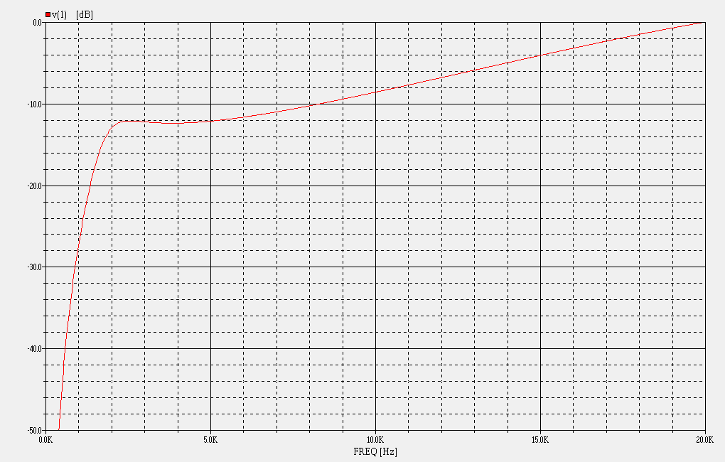
The way I do it is to slightly underdamp the splitter filter. This lifts the region right around the crossover frequency, just enough to get the first octave or so flat, up to mass rolloff. The amount of damping should be chosen specifically for the horn/driver used, as this is where they are the most different. Some horns have more peaking down low, others have less. The goal is to use a horn that is not peaking at all, and then to use a filter with this transfer curve:
Inductors tend to resist change of current flow through them. Current flowing through them generates a magnetic field around them, storing the energy in the field. When current flow is reduced, the magnetic field collapses into the coil, putting energy back into the circuit. This has a current stabilizing effect.
Capacitors tend to resist the change of voltage across them. When voltage is applied across the plates, energy is stored in the dieletric between them. If the voltage across the plates is reduced, the dielectric discharges, releasing energy into the circuit. This has a voltage stabilizing effect.
Resistors resist the flow of current and the change of voltage across them equally. They simply impede current flow through them.
When an inductor and capacitor are placed in a circuit, they resonate at a certain frequency. If there is no resistance in the circuit, the resonant peak will be very high and the bandwidth of the peak will be narrow. Adding resistance to the circuit reduces the amplitude of the peak, but widens the frequency range of the peak. This is called damping.
You can see how these things interact in the documents below:
- Speaker Crossover Document
- "Crossover Electronics 101" Seminar Handouts
- "Crossover Electronics 101" Audio file
1. Provide SPL level matching
2. Provide top-octave augmentation
3. Provide a flat shelf up to mass rolloff
The way I did this was to first use a resistive voltage divider network (fixed L-Pad) to attenuate the passband, and bypass the series resistor with a capacitor to provide 6dB/octave augmentation. You could do this with textbook L-Pad values, except that would not satsfy goal #3.
The compression driver is flat up to mass rolloff, around 4kHz. Only above that point do you want the diagonal line of rising response. That's the problem with most CD equalization schemes in active crossovers - if you jumper in CD EQ, you get a diagonal line of rising response. That may work with some horns, if there is enough of a quarter-wave mode around the crossover frequency to boost the bottom end enough to make the whole tweeter passband have falling response. But I'm not sure I'd want to crossover to a tweeter horn in an area where it had quarter-wave modes, because that's probably too low for it to sound good.
So there's the rub. If you have the top-octave compensation filter providing 6dB/octave augmentation, then you need something to flatten out the bottom end, up to 3kHz.
The way I do it is to slightly underdamp the splitter filter. This lifts the region right around the crossover frequency, just enough to get the first octave or so flat, up to mass rolloff. The amount of damping should be chosen specifically for the horn/driver used, as this is where they are the most different. Some horns have more peaking down low, others have less. The goal is to use a horn that is not peaking at all, and then to use a filter with this transfer curve:
Wayne,
Please explain what "damping" means in this context, I've been struggling with this concept a while and I know it's an elementary part of circuit design, but it's not clicking.
I understand initial attenuation of the hi-pass is required to allow the compensation filter latitude to "remove" attenuation in the conjugate of the rolloff above 3 or 4 kHz.
When you say the "core" crossover in your designs is allowed to be underdamped, I visualize less attenuation at the crossover point, but now I think it refers to the slope of the filter. To make the shelf flatter, the slope has to be sharper, or steeper -- this gives a flatter initial response to mass rolloff because the filter has less-gradual rise from the core filter.
So does an underdamped higher impedance load provide this?
Sorry to be basic.
Wayne Parham
Active Member
Work with the JBL 6" x 6" PT. If the performance curves shown by JBL are correct, I don't believe there are many others that can match its CD performance, and three of us have now confirmed how good it sounds.... :thmbsp:
And again, if crossover is made much higher, say at 3kHz or above, I suggest looking at a slightly different HF network. I'd probably reduce the values of the resistors in the voltage divider a smidge, to increase damping. If the crossover frequency is that high, then the driver is operated entirely in the region above mass rolloff. In that case, I'd want the HF circuit transfer function to be a straight diagonal line at 6dB/octave.
What we have in the existing crossover is an initial flat shelf followed by rising response at mass rolloff. When crossover is below 3kHz, we have two regions to cover, one above and another below mass rolloff. That's why we use R1/R2 values that slightly underdamp the HP splitter filter in the tweeter circuit.
I may have gotten too wordy explaining the "why" in my earlier post so the "how" might have been missed.

Wayne Parham
Active Member
I'm still listening to the PH612 horns with D210Ti drivers and Kef B110 and AR3a woofers. I've changed around the crossover scheme. I decided to go for a higher crossover point from mid to tweeter. Using a 3-way active xovr I now have the crossover points set at 200 hz and 3khz. The only passive filtering in the system now is the CD compensation for the treble.
This way the B110 is doing the bulk of the important work, handling everything from 200 to 3K. I think the midrange might need some notch filtering on it. The FL6-23 LS3/5A crossover puts in series with teh B110 a parallel combination of 6.2uf, 2.67 mh and 33 Ohms. IIRC, Fc= 1/(2 pi (sqrt(LC)) so the center freq should be 1250 hz. I can hear a little prominence in the mids so maybe I'll try out that notch filter if I can round up the right inductors.
Here's a question about the CD compensation. This consists of 15 Ohms in series, bypassed with .47uf, and 24 - 30 Ohms in parallel. If the crossover point is raised, what effect does this have on the CD compensation? Do the component values have to be changed? My gut says 'no' but I thought I'd ask.
One thing I just noticed - You're running active, so are you just using R1/R2 and the bypass capacitor (C1 in my schematics)? If so, you have a straight line of rising response. As I said earlier, that's probably what I would want when crossing over at 3kHz or higher.
Out of curiosity, is there CD EQ built-in on your active crossover? If so, maybe try it?
Bauhausler
Rational Subjectivist
Wayne;
Thanks again for your very comprehensive contributions. You answered all of the questions that I asked, and also the ones that I thought of after I hit 'Post'.
The active XO that I'm using does not have built in CD EQ. I might have one here that does that but I chose to use this out of laziness. It has 2 channels and 3 bands and was already in the rack and plugged in. I have so much gear it might have taken an hour to look for a Rane or something, then recall that I lent it out.
This XO has relatively crude controls. It's all 18 db/octave. the mid/hi XO point is 900/1K/2K/3K/4K/5K/6K/7K/8K/9K/10K. With this driver selection that gives us basically 2K, 3K and 4K, and 4K is a bit high for the B110. I'm running it at 3K and 200Hz. The levels are set by ear, which usually means way too much bass so it sounds well balanced when turned down to background levels.
I like the way this is sounding. I installed the D220Tis in place of the D210Tis and I *think* there's a little more air and sizzle on top. It certainly isn't lacking with the D220Tis and with the D210Tis it sometimes seemed a little rolled off at the top.
Regarding the CD compensation and its interaction with the Lvc, it seems like the compensation should change a bit with the position of the Lpad. When the driver level is turned down with the Lpad the 'driver' load becomes more resistive and less inductive. I haven't given that much thought but when it's driven from anything but a pure voltage source it would make a difference in the transfer function to the VC.
I think.
Thanks again for your very comprehensive contributions. You answered all of the questions that I asked, and also the ones that I thought of after I hit 'Post'.
The active XO that I'm using does not have built in CD EQ. I might have one here that does that but I chose to use this out of laziness. It has 2 channels and 3 bands and was already in the rack and plugged in. I have so much gear it might have taken an hour to look for a Rane or something, then recall that I lent it out.
This XO has relatively crude controls. It's all 18 db/octave. the mid/hi XO point is 900/1K/2K/3K/4K/5K/6K/7K/8K/9K/10K. With this driver selection that gives us basically 2K, 3K and 4K, and 4K is a bit high for the B110. I'm running it at 3K and 200Hz. The levels are set by ear, which usually means way too much bass so it sounds well balanced when turned down to background levels.
I like the way this is sounding. I installed the D220Tis in place of the D210Tis and I *think* there's a little more air and sizzle on top. It certainly isn't lacking with the D220Tis and with the D210Tis it sometimes seemed a little rolled off at the top.
Regarding the CD compensation and its interaction with the Lvc, it seems like the compensation should change a bit with the position of the Lpad. When the driver level is turned down with the Lpad the 'driver' load becomes more resistive and less inductive. I haven't given that much thought but when it's driven from anything but a pure voltage source it would make a difference in the transfer function to the VC.
I think.
Last edited:

hhibrownsbac
Super Member
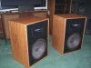
I thought maybe some of you might like too see these. My second set of econowaves is finished and I am at a loss for words. These might not be econo but they were sure worth it. I have spent the afternoon listening to these after finishing them up this morning and I absolutely couldnt be happier. Its amazing what a couple sheets of plywood, some TLC and a couple 2225Hs and DE 250s can end up as. Im still using the standard Crossover but ordered the upgrades Zilch suggested, But I cant possibly imagine these sounding much better. The cab is a copy of the 4507 other than I moved the ports down a inch in case I ever need more room. These things are so sweet I cant get the smile off of my face. I wonder how they would sound "stacked", here we go again. I sincerely would like to thank each and every person who has contributed to this thread. You guys are great and like I said before i couldnt have done this in a million years without all your help!!!!! The wealth of information buried in this thread is just truely amazing.
Attachments
Last edited:
hhibrownsbac
Super Member
You got that right, I didnt see a armadillo, rabbit, squirrell, deer or anything else today, they were running for cover:thmbsp:. Its speakers like these that make you appreciate living somewhere that the closet neighbor is a mile away.EXCELLENT, Hhi!
And those'll rock the neighborhood too, if desired....

von.ah
Schultze!
Pants Excess is really FAST at delivering parts here.
This gave me a healthy chuckle...
Russellc
Addicted Member
I thought maybe some of you might like too see these. My second set of econowaves is finished and I am at a loss for words. These might not be econo but they were sure worth it. I have spent the afternoon listening to these after finishing them up this morning and I absolutely couldnt be happier. Its amazing what a couple sheets of plywood, some TLC and a couple 2225Hs and DE 250s can end up as. Im still using the standard Crossover but ordered the upgrades Zilch suggested, But I cant possibly imagine these sounding much better. The cab is a copy of the 4507 other than I moved the ports down a inch in case I ever need more room. These things are so sweet I cant get the smile off of my face. I wonder how they would sound "stacked", here we go again. I sincerely would like to thank each and every person who has contributed to this thread. You guys are great and like I said before i couldnt have done this in a million years without all your help!!!!! The wealth of information buried in this thread is just truely amazing.
I knew you were going to dig those, I still have the smile everytime I fire them up. Did you take pics along the way?
Russellc
Wayne Parham
Active Member
Wayne;
Thanks again for your very comprehensive contributions. You answered all of the questions that I asked, and also the ones that I thought of after I hit 'Post'.
The active XO that I'm using does not have built in CD EQ. I might have one here that does that but I chose to use this out of laziness. It has 2 channels and 3 bands and was already in the rack and plugged in. I have so much gear it might have taken an hour to look for a Rane or something, then recall that I lent it out.
This XO has relatively crude controls. It's all 18 db/octave. the mid/hi XO point is 900/1K/2K/3K/4K/5K/6K/7K/8K/9K/10K. With this driver selection that gives us basically 2K, 3K and 4K, and 4K is a bit high for the B110. I'm running it at 3K and 200Hz. The levels are set by ear, which usually means way too much bass so it sounds well balanced when turned down to background levels.
I like the way this is sounding. I installed the D220Tis in place of the D210Tis and I *think* there's a little more air and sizzle on top. It certainly isn't lacking with the D220Tis and with the D210Tis it sometimes seemed a little rolled off at the top.
Regarding the CD compensation and its interaction with the Lvc, it seems like the compensation should change a bit with the position of the Lpad. When the driver level is turned down with the Lpad the 'driver' load becomes more resistive and less inductive. I haven't given that much thought but when it's driven from anything but a pure voltage source it would make a difference in the transfer function to the VC.
You're right about the L-Pads and that's one of the reasons I don't use them. I do see why others would though. There are advantages and disadvantages, I suppose, just like so many other things. It's a matter of personal preference more than a "right way" and a "wrong way".
Two-way speakers are nice because they're simple. But three-way speakers have certain advantages.
I love my three Pi and four Pi speakers, which are DI-matched two-way speakers like what most people are doing here. But my six Pi and seven Pi three-way constant directivity speakers are even better. There are several advantages they offer, from extending the uniform directivity control way down in frequency to reducing IMD to smoothing the upper modal region by overlapping the mids and the woofers. I encourage everyone here to experiment with this approach.
Here are several threads with info on three-way CD speakers, midhorns and corner loading. There's some good info buried in those threads. If you think about it, the corner limits the radiating angle to 90°, so putting your speakers there provides constant directivity all the way down to the Schroeder frequency. Not everyone can take advantage of this, some room layouts just don't make cornerhorns appropriate. But if you have the right room, a CD cornerhorn can't be beat.
- Midrange Horn
- Higher cut-off for 7pi (comments on cone drivers verses compression driver for mids)
- Pi Midrange Horn (more comments on cones for midhorns)
- Pi Cornerhorns - a brief history
- Pi horn design philosophies
- Corner Horn positioning "Sweet Spot" for listening
- Making speakers "disappear"
- Recommended toe in
- Cornerhorn implementations
- 7pi and listening room considerations
- Positioning and subs
- Imaging, placement and orientation
- Phase angles, crossovers and baffle spacing
- Baffle spacing, phase angles and time alignment, revisited
- Matching directivity in the vertical and the horizontal planes
- Baffle spacing, null angles, etc...
- K-Horn/ Pi-Horn Differences
- Klipschorn vs seven Pi cornerhorn
Wayne Parham
Active Member
Its amazing what a couple sheets of plywood, some TLC and a couple 2225Hs and DE 250s can end up as.
No doubt! When properly implemented, I'd say that combination sounds better than 99% of the speakers on the market today.
Enjoy!