• The move to the new server is done. There are some software and database maintenance updates in process. This has us passing the hat around to help out. We appreciate any donations. Seriously, even a dollar helps. The payment page may be found here - https://www.audiokarma.org/support.html

Zilch's AK Design Collaborative - Econowave Speaker

JBL 6" waveguide/2414H and B110 woofer

I'm running this combo with teh standard ewave low sensitivity crossover now. The Lpad is turned way down because of the B110's low sensitivity. Tonally, it seems to work. I'll measure later, but I think I should make a shorter mic cable, as this long one appears to be losing HF. More later. I'm going a little blind right at the moment due to a visual cortex migraine spazzing out my vision.
 
I'm getting pronounced ringing in the PE KDT cabinets. My question is, will fiberglass fill eliminate this? Or is bracing required? I will run a sweep to find it's exact frequency probably tomorrow. I'd guess at 500Hz.:dunno:
 
I'm getting pronounced ringing in the PE KDT cabinets. My question is, will fiberglass fill eliminate this? Or is bracing required? I will run a sweep to find it's exact frequency probably tomorrow. I'd guess at 500Hz.:dunno:
Very likely the fiberglass will mitigate the standing waves inside the cab -- that's its job.

Bracing's not a bad idea either, but it's difficult to get a solid connection to the front baffle if that's removable, and if you build it right, all snug and all, it's kinda tough to rear mount a woofer in there.... ;)
 
I need to get into gear.
My components will be here from PE tomorrow and my waveguides will be here Wednesday.
I have decided on a 3 cubic foot enclosure tuned to 30 hz. Now I need to go buy materials and get to work on it.
 
I'm ready to mark the holes for the driver cutouts. Is there a link to a template for the JBL waveguide, or dimensions? I know the outside dimensions are 11.9 x 6.4".
 
Cool beans. This is getting me excited!

How deep is the "countersink" for flush mounting?

Oh, and one more thing: what's the conventional wisdom on port placement--do you want to have them away from the sides of the cabinet, or is 3/4" from the bottom OK? (2 ports @ 3" ID x 11.25", 3.5" OD)
 
Last edited:
Interior opening one duct diameter away from surfaces. Even if the duct itself is closer to them, that may be achieved with an elbow of appropriate angle at the end. Call it a "flare" if you like. Don't aim it at the back of the woofer, tho, 'cause it'll pick up midrange and "port" it out.

http://www.eighteensound.com/staticContent/applications/kits/18Sound_kit15.pdf

Note how close the ports appear to be to the walls and bottom on P. 2, then what's actually happening on P. 4.

Waveguide flange thickness varies between 0.160" and 0.180", but you'll have a gasket or foam tape behind it, so 0.1875" recess, 3/16". Caution on the outside dimensions; I don't believe they are as stated in the spec. Measure or trace from the actual piece. You'll want to do that to get the corner radius correct anyway.... :yes:
 
Last edited:
Econowave addiction?

After building a 12" Selenium 12PW3 pair of the EWave and being very satisfied with it, now I am drooling over the possibility of a 15" woofer version to eek out an even bigger sound. Having a pair of 15" driver boxes in the family room is not good for WAF, but the thought of having that much displacement makes me drool :D

Is there any hope for this addiction? :tongue:
 
Last edited:
So a 3" port would need to be positioned at least 3" away from the side walls (all else being the same)?

Also, is flush mounting a big deal, since the baffle has a trim piece running vertically up either side? Would this negate any baffle step gains made by flush mounting the drivers?
 
That 18Sound build looks great according to their published data, don't u think? I didn't think the vertical polars would look as good as they show, if they are legit, because the waveguide is so tall and the crossover is not so low....

Zilch, I noticed they put the conjugate filter ahead of the high pass filter. :dunno:


Interior opening one duct diameter away from surfaces. Even if the duct itself is closer to them, that may be achieved with an elbow of appropriate angle at the end. Call it a "flare" if you like. Don't aim it at the back of the woofer, tho, 'cause it'll pick up midrange and "port" it out.

http://www.eighteensound.com/staticContent/applications/kits/18Sound_kit15.pdf

Note how close the ports appear to be to the walls and bottom on P. 2, then what's actually happening on P. 4.

Waveguide flange thickness varies between 0.160" and 0.180", but you'll have a gasket or foam tape behind it, so 0.1875" recess, 3/16". Caution on the outside dimensions; I don't believe they are as stated in the spec. Measure or trace from the actual piece. You'll want to do that to get the corner radius correct anyway.... :yes:
 
That 18Sound build looks great according to their published data, don't u think? I didn't think the vertical polars would look as good as they show, if they are legit, because the waveguide is so tall and the crossover is not so low....

Zilch, I noticed they put the conjugate filter ahead of the high pass filter. :dunno:

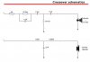
R parallel with C looks like the compensation component, as it raises the level with increasing frequency.

attachment.php
 

Attachments

  • Imagea1.jpg
    Imagea1.jpg
    42.3 KB · Views: 277
Last edited:
R parallel with C looks like the compensation component, as it raises the level with increasing frequency.

The 27 Ohm and 1.5 microfarads are indeed the HF compensation components, and correspond to R1 and C3 in the EconoWave crossover schematics. R2 is not required in the 18Sound version since compensation and level correcting happen right at the input, which would be driven by the low impedance output of the driving amplifier. In the EconoWave, level correction and HF compensation are done after the crossover, and R2 is necessary to return the driven load seen by the crossover back to the impedance it would have been without the addition of R1 and C3.
 
After building a 12" Selenium 12PW3 pair of the EWave and being very satisfied with it, now I am drooling over the possibility of a 15" woofer version to eek out an even bigger sound. Having a pair of 15" driver boxes in the family room is not good for WAF, but the thought of having that much displacement makes me drool :D
A 15" has 90° horizontal dispersion at ~1 kHz. If a design objective is directivity matching the LF and HF, and the waveguide is 90°, that's where the crossover wants to be in the interest of coherency in this region.

A major deal? Naw, a refinement, is all.

So a 3" port would need to be positioned at least 3" away from the side walls (all else being the same)?
The inner entrance, yes.

Also, is flush mounting a big deal, since the baffle has a trim piece running vertically up either side? Would this negate any baffle step gains made by flush mounting the drivers?
For the most part, yes. In the case of the QSC in the PE traps, however, flush mounting the waveguide permits rounding over a rear-mounted woofer opening without increasing the center/center distance, the waveguide flange being incorporated as part of the roundover.

That 18Sound build looks great according to their published data, don't u think? I didn't think the vertical polars would look as good as they show, if they are legit, because the waveguide is so tall and the crossover is not so low.
They rather suck in the crossover region, actually; looks like the vertical nodes narrow the forward lobe to ~20° at -6 dB.

Peruse the other kits there. The 8" with XT120 and 12" using XT1086 behave much better in this respect. :yes:

Zilch, I noticed they put the conjugate filter ahead of the high pass filter. :dunno:
Yes, a different approach than Wayne uses, commonly employed by JBL. For example, look how I parsed the Timbers comp filter some years ago here:

http://audioheritage.org/vbulletin/showthread.php?p=145641&postcount=73
 
Last edited:
I went to Lowes today and bought my mdf . I have all the enclosure parts cut now.
Tomorrow I will do the router work and start the glue up process.
UPS left me 5 boxes of JBL waveguides while I was gone :)
All this after a long day at work starting at 6 this morning.
Yep , I want to hear these things soon.
 
They rather suck in the crossover region, actually; looks like the vertical nodes narrow the forward lobe to ~20° at -6 dB.

Peruse the other kits there. The 8" with XT120 and 12" using XT1086 behave much better in this respect. :yes:

Yes, I see it now. You're right. The horn is just too damn tall and crossover too high. The QSC forward lobe does seem a little narrow in the vertical to me in my test setup. Has someone measured QSC in system for vertical nulls?

Yes, a different approach than Wayne uses, commonly employed by JBL. For example, look how I parsed the Timbers comp filter some years ago here:

http://audioheritage.org/vbulletin/showthread.php?p=145641&postcount=73

I hadn't noticed that. Does the different approach yield a different result compared to putting the HP ahead of the conjugate filter?

I see your Lansing post. Stupid question...what were you doing there? Trying to reverse engineer the compensation from measurements of individual components, then making sims?

Time for another one of these:dunno:
 
Yes, I see it now. You're right. The horn is just too damn tall and crossover too high. The QSC forward lobe does seem a little narrow in the vertical to me in my test setup. Has someone measured QSC in system for vertical nulls?
Yes, Brandon has:

http://www.avsforum.com/avs-vb/showthread.php?p=17187889#post17187889

He's not done yet, but it looks like he's only got a 20° forward lobe (-6 dB) crossing at 1.3 kHz, I believe he's using. Not as good a Catapult's sim; there's more to be done, clearly.

I hadn't noticed that. Does the different approach yield a different result compared to putting the HP ahead of the conjugate filter?
It's a different art, and both may be applied to produce substantially the same or a similar result, at least insofar as frequency response is concerned.

I started applying the Timbers approach to eWave back on Page 1, Post #4, where you see I had dialed it in well up to 10 kHz:

http://www.audiokarma.org/forums/attachment.php?attachmentid=80392&d=1203902510

It would easily have required many more parts than Jack's adaption of Wayne's Pi-Speaker crossover, so we ran with that, instead.

I see your Lansing post. Stupid question...what were you doing there? Trying to reverse engineer the compensation from measurements of individual components, then making sims?
My LHF pal Giskard posted Greg's comp filter for the JBL H4338 using the 435be driver, and suggested I might tweak it for other similar combinations, which required me to parse it in Spice in order to understand how it worked. If you follow the saga from there, you'll see I did that for JBL 2435HPL on H9800 and PT waveguides. Euro members built with it right away; it's only recently that "locals" have caught on.... :thmbsp:
 
Last edited:
Thanks, Zilch.
I'll look more at the LHF stuff. Beryllium drivers on JBL consumer horns may be a bit heady, and moot at my means, but maybe I can learn something. I'll see how you applied those filters to the PT guides.

Straight up, I will move off the QSC guide if the lobe is not reasonable. I'm working on the bass bin first, as that will remain, most likely.

On axis, it is very nice sounding, though. I'l break out the Z-19 model 19 crossover to see if the DE250/QSC sounds good lower to my ear.
 
Last edited:
Thanks, Zilch.
I'll look more at the LHF stuff. Beryllium drivers on JBL consumer horns may be a bit heady, and moot at my means, but maybe I can learn something. I'll see how you applied those filters to the PT guides.

Straight up, I will move off the QSC guide if the lobe is not reasonable. I'm working on the bass bin first, as that will remain, most likely.

On axis, it is very nice sounding, though. I'l break out the Z-19 model 19 crossover to see if the DE250/QSC sounds good lower to my ear.

How are you measuring this lobe? As to the 20 degree lobe, cant that be manipulated via the crossover? I thought ( and what I dont know would fill a battleship) the crossover was one of the main things which determined the frontal lobe. I dont notice the highs falling off standing up, is this just a measurement thing or have you had listening problems as well?

Doesnt a zobel alter the frontal lobe as well? Or does the crossover just change the position of the lobe, and not alter how large it is? I've really enjoyed the QSC wave guide and havent found anything that I prefer the JBL wave guide over the QSC.......yet.

Russellc
 
How are you measuring this lobe?
http://www.audiokarma.org/forums/showthread.php?p=2867674#post2867674

The full height (width) of the forward lobe is delineated by the null maxima, and its nominal effective height by the -6 dB points either side of the forward axis. The primary variables are the center-to-center distance between the drivers and the frequency at crossover. The "tilt" of the forward axis from normal (perpendicular to) the baffle varies with the difference between the distances of the acoustic centers of the drivers behind it, and their relative phase as established by the crossover filters.

If we calculate the vertical listening window from a typical listening distance, I believe we'll find 20° to be quite acceptable, provided the forward axis is optimized. As Wayne has extensively discussed on this and other forums, it is also desirable to have the nulls themselves coincide with the vertical beamwidth of the waveguide so as to augment the vertical pattern control.

Despite its larger size, the QSC waveguide does not exhibit better directivity or pattern control than the standard eWave; much of that larger dimension is dedicated to mouth roundover, itself a desirable feature. That also increases the C/C distance between the drivers, however, and for any given crossover frequency, narrows the forward lobe. Others have argued that these differences are inconsequential -- Geddes, for example, claims he doesn't care. He has no option, really.

So, we're talking tradeoffs and compromises here, and the rubber is hitting the road. I believe everyone who has heard it likes how this combination performs in terms of sonic quality; we want to work it optimally. As Skywave would like to determine, how low can DE250 competently play on the QSC waveguide? Will the locations of the nulls at a lower crossover frequency effectively compensate for the consequential losses in vertical pattern control? :dunno:

http://www.audioheritage.org/vbulletin/showthread.php?p=75815#post75815
 
Last edited:
Back
Top Bottom