• The move to the new server is done. There are some software and database maintenance updates in process. This has us passing the hat around to help out. We appreciate any donations. Seriously, even a dollar helps. The payment page may be found here - https://www.audiokarma.org/support.html

Zilch's AK Design Collaborative - Econowave Speaker

Wow, I looked at a link in there to a guy who bought the Nathan kit and saw what a POS that $1200 cabinet was.
Anybody who sells a kit for $1200 and then tells buyers they need to putty and sand it to make it fit right should be drawn and quartered. :yes:
 
You don't need to be a rocket scientist to deduce that compliants from customers on a public forum and with pictures is bad for business.
 
You don't need to be a rocket scientist to deduce that compliants from customers on a public forum and with pictures is bad for business.
He's NOT a rocket scientist, rather, a "Physicist." with a capital "P."

My issues are with the performance. EconoWave beats his waveguide, by his own standards and measures, even in its most refined implementation.

He'll rationalize anything in his own interest, and there's obviously no dearth of suckups to believe him.... :yes:
 
hi jackgiff

i'm using jbl k120's that are 101db or k110's at 98db and later add the to me 2235's

For the woofer components, no changes are necessary. Refer to the EconoWave crossover for "woofers greater then 95 Db", dated 4-05-08. L2 and C2 are unchanged. C1 becomes 2.34 Microfarads (a 2 Microfarad in parallel with a .33 Microfarad is close enough). L1 becomes a 1.2 Millihenry.

The D220Ti is spec'ed to be about 109 DB on a horn, so you will need to throw away roughly 6 DB, which will leave the ability to adjust the tweeter just a bit higher than the woofer with the L-pad. Since I don't have any of your drivers to test with, I would start with R1 equals 15 ohms, which should throw away about the proper amount. R2 should be 33 Ohms. The compensation capacitor C3 would be about right at .68 Microfarads.

The resistors may need some tweaking, but this should be very close. Let us know how they sound.
 
He's NOT a rocket scientist, rather, a "Physicist." with a capital "P."

My issues are with the performance. EconoWave beats his waveguide, by his own standards and measures, even in its most refined implementation.

He'll rationalize anything in his own interest, and there's obviously no dearth of suckups to believe him.... :yes:

rocket scientist just a figure of speech not literal...
 
He's NOT a rocket scientist, rather, a "Physicist." with a capital "P."

...and there's obviously no dearth of suckups to believe him.... :yes:

Can you imagine what they would look like if he was just a physicist.

And maybe his suckups are just guys who don't have the balls to try a project on their own. It is easier to say, "Yes Earl, Yes Earl, three bags full", than to build something for yourself. Not nearly as satisfying, however.
 
They're "Believers," in my view, in the larger sense.

Is there somewhere in all of the hype leading up to his point that they were advised to expect substandard quality and derated performance for $1200? :dunno:
 
Jack, are your JackLab compensated crossover boards suitable for E'Wave builds?

attachment.php
 

Attachments

  • JackLab Xover.jpg
    JackLab Xover.jpg
    26.8 KB · Views: 311
Jack, are your JackLab compensated crossover boards suitable for E'Wave builds?


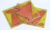
Yes indeed. I had been just tacking on the compensation parts to the older pc boards, but decided to make a new layout. This one has a third order hi pass, but the last capacitor can just be replaced with a jumper to build the entire EconoWave crossover.

Maybe a third order hi pass will be suitable for the EconoWave as well. When the present project is finished, I will try that. Another way to skin a cat?

If photography is successful, copies of the layout will be available to builders who want to etch their own circuit boards. It is not rocket science, and can be very satisfying.
 
Jack, are your JackLab compensated crossover boards suitable for E'Wave builds?

attachment.php

We need a circuit board tutorial!:yes: This projects ability to educate just doesnt stop.:music: This will be great for the CC crossover I am now building. Unfortuately, my last order was missing a couple of items, but they should be here by weds.

Russellc
 
I'm clueless as to the process, but am sure I can pick it up. What I am woefully unprepared tp do is make a layout that fits the intended parts. Off to Rat Shak for 1.5 meg resistors, 9 volt battery snaps, and 9 volt battery mounts.:thmbsp:

Russellc
 
For the woofer components, no changes are necessary. Refer to the EconoWave crossover for "woofers greater then 95 Db", dated 4-05-08. L2 and C2 are unchanged. C1 becomes 2.34 Microfarads (a 2 Microfarad in parallel with a .33 Microfarad is close enough). L1 becomes a 1.2 Millihenry.

The D220Ti is spec'ed to be about 109 DB on a horn, so you will need to throw away roughly 6 DB, which will leave the ability to adjust the tweeter just a bit higher than the woofer with the L-pad. Since I don't have any of your drivers to test with, I would start with R1 equals 15 ohms, which should throw away about the proper amount. R2 should be 33 Ohms. The compensation capacitor C3 would be about right at .68 Microfarads.

The resistors may need some tweaking, but this should be very close. Let us know how they sound.

Jackgiff:
Could you explain to me the changes to the crossover you are suggesting?
Which woofer are you discussing, his 101 db or the 98, or his soon to get 2235s? I understood that over 95 db resulted in crossover dated 4-5-08,
what are these changes, i.e. "C1 becomes 2.34 Microfarads." "L1 becomes a 1.2 Millihenry" ( and changing R2 to 33 ohms. ) doing for the cross over and how are you calculating this? Are these changes if he uses the 16 ohm selenium? That would explain things.:scratch2:

Thanks,
Russellc
 
Jackgiff:
Could you explain to me the changes to the crossover you are suggesting?
Which woofer are you discussing, his 101 db or the 98, or his soon to get 2235s? I understood that over 95 db resulted in crossover dated 4-5-08,
what are these changes, i.e. "C1 becomes 2.34 Microfarads." "L1 becomes a 1.2 Millihenry" ( and changing R2 to 33 ohms. ) doing for the cross over and how are you calculating this? Are these changes if he uses the 16 ohm selenium? That would explain things.:scratch2:

Thanks,
Russellc

Hi Russell,

The changes for C1 and L1 are to use the 16 Ohm Selenium driver, rather than an 8 Ohm version. The changes to the two resistors are necessary because of the 16 Ohm driver as well, but since his woofers have such high SPL's, they were recalculated to get his L-Pad setting closer to the Norm position. And of course the change to the compensation cap is necessary because of the different impedance of the HF driver.

I just used the 101 Db figure to calculate the resistor values. The 98 Db one should also fit.
 
Hi Russell,

The changes for C1 and L1 are to use the 16 Ohm Selenium driver, rather than an 8 Ohm version. The changes to the two resistors are necessary because of the 16 Ohm driver as well, but since his woofers have such high SPL's, they were recalculated to get his L-Pad setting closer to the Norm position. And of course the change to the compensation cap is necessary because of the different impedance of the HF driver.

I just used the 101 Db figure to calculate the resistor values. The 98 Db one should also fit.

Thanks for the clarification!:thmbsp:

Russellc
 
New crossovers assembled.

Here are the new crossover pc boards assembled, as they will be used in my nephews speakers. The third order hi pass will be tested next for the EconoWaves, and may offer some advantages over the second order used in the existing crossover. Or it may just add cost. If so, the capacitor on the right can just be replaced with a jumper.
 

Attachments

  • newxover1.jpg
    newxover1.jpg
    33.6 KB · Views: 131
Back
Top Bottom