• The move to the new server is done. There are some software and database maintenance updates in process. This has us passing the hat around to help out. We appreciate any donations. Seriously, even a dollar helps. The payment page may be found here - https://www.audiokarma.org/support.html

Zilch's AK Design Collaborative - Econowave Speaker

No tape measure at hand in my storage unit, but when I fit the WaveGuide into the Utility Cabinet there's about 1/4" of clearance on each side between the cabinet edge; it fits fine.
That's great news as we can now hack up these lesser cabs rather than the nice walnut ones if we like the sound of the EWG laying on top.

Thanks, Andyman. I think a LargeEWGAdvent would be a worthwhile project. Probably not in the realm of the ultimate quality of Altec or JBL based systems, but it has these factors on its side:

1) Full range. The Large Advent has plenty of low bass. Some of the smaller high sensitivity woofers are weak below 60 hz and that's not enough for my room.
2) Common. Nearly anyone can turn up a pair of used Advent cabs & a pair of woofers.
3) Horn fits in cabinet. A much more compact package for domestic use.
4) Easy to work on. Not too large or heavy for moving around & modding.
5) Cheap.

Okay, I'll bite. After I get the drivers & scrounge some crossover parts I'll put together a pair of EWG 2-ways using a pair of Utility cabinets. I don't know which woofers I'll use yet. It will probably depend on which ones don't need re-foaming.
LVB has a pair of cabs that I'm sure he'd be delighted to get out of his garage. I think between us we have about 7 woofers.
I only have about 11 other speaker projects to do so I might as well make this one about priority #2. I'll start dragging the parts together today.
 
Sounds cool!
I'm no crossover guru, but something tells me that the 107 dB Seleniums might be a little more efficient than Henry's fried egg and will need to be reigned in a bit. Then again, I'm pretty sure Zilch has a couple (??) schematics posted that might fit the bill.

Keep us posted! I'll be messing around with my Altecs first with them, just because that's my hot button right now.
 
I checked last night. The JBL E'Wave PT waveguide will easily fit in the OLA utility cab, which is 12.375" here. I don't have the Pyle issue to try.

It will also fit my LA cabinet (just) after removing the vinyl trim. Notch the trim over the flange on reinstallation.

Y'all're shameless heretics.

[I hope this works stunningly.... :p: ]
 
I'm no crossover guru, but something tells me that the 107 dB Seleniums might be a little more efficient than Henry's fried egg and will need to be reigned in a bit. Then again, I'm pretty sure Zilch has a couple (??) schematics posted that might fit the bill.
Some of that SPL "headroom" is used by the E'Wave crossover to flatten the response via HF compensation. It's contoured midband attenuation which accomplishes that, and two crossover versions are provided to balance the remainder with woofers of higher vs. lower efficiencies....
 
I checked last night. The JBL E'Wave PT waveguide will easily fit in the OLA utility cab, which is 12.375" here. I don't have the Peavey issue to try.

It will also fit my LA cabinet (just) after removing the vinyl trim. Notch the trim over the flange on reinstallation.

Y'all're shameless heretics.

[I hope it works stunningly.... :p: ]

I compared the Pyle (exactly 12.00" across) to a 'New' (rounded edge) LA cabinet and there's 3/16" of interference with the wood rim, excluding the vinyl. My pair of 'original' veneered LA's is in the closet & not available for measuring. I assume that's what you measured, Zilch. We already know it will fit the Utility. So I'll try the project on a set of Utilities first. If it's stellar and desirably permanent I'll toss teh vinyl cabs & do the necessary mods to make it work on a set of veneered ones.

I might try something tricky like pasteboard as a thick-ish gasket behind the rim of the horn. The metal frame woofer has a very thin rim with no raised edge and it might be possible to overlap the horn over the edge of the woofer, achieving a very close distance between the centers of the drivers. I gather that's desirable.

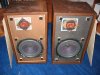
Looking at the photo of the Utility (below) the tweet is set so high that its hole may have to be fully or partially filled to mount the horn much lower.

Another thing I'd do is hog out the terminal cup on the back so I could build the whole xovr on a piece of masonite and screw it to the back of the cab from the outside.

I'm about to start syringing glue onto a new set of surrounds for the metal-framed woofers I'll be using.
 

Attachments

  • 111_1131C.jpg
    111_1131C.jpg
    52.6 KB · Views: 65
I might try something tricky like pasteboard as a thick-ish gasket behind the rim of the horn. The metal frame woofer has a very thin rim with no raised edge and it might be possible to overlap the horn over the edge of the woofer, achieving a very close distance between the centers of the drivers. I gather that's desirable.
In my view, minimizing edge diffraction of the waveguide is more important than squeezing the last available bit out of center distance.

See my pic @ #813, above, and also some of Jack's baffles. He recesses the waveguide flush.

I'm hoping Wayne will step forward with the answer; from his commercial designs, though, it's apparent he doesn't consider center distance that critical an issue:

http://www.pispeakers.com/catalog/product_info.php/products_id/97

OLA - Utility:

attachment.php

Tweeters were high on my LAs, too:

attachment.php

I'd say covering the existing tweeter hole would be controlling from an ease of retrofit perspective.... :yes:
 
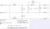
Crossover schematics in Cad

Sounds cool!
I'm no crossover guru, but something tells me that the 107 dB Seleniums might be a little more efficient than Henry's fried egg and will need to be reigned in a bit. Then again, I'm pretty sure Zilch has a couple (??) schematics posted that might fit the bill.


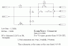
Here are the two crossover schematics for the EconoWave project. The first is for woofers with SPL's less than 95 Db, and the second is for woofers with SPL's greater than 95 Db. These are the same as the hand drawn and photographed copies from earlier in the thread.

I am just learning CAD, and can't get the schematics into a format which is acceptable to the forum, except by converting them to Microsoft Word documents, but then they won't open in the forum window. If you have Word, or a program which can open Word DOC's, you can see them. Maybe someone can tell me how to get them into a format which is more acceptable to the AK forum.

I also have a PC layout CAD program, and will spend some time learning it. Maybe it will possible for one of us to order PC boards, and sell them to everyone for about the same cost as etching your own. But we need Gerber files, or equivalent to order the boards from the China PC company that is an advertiser on AK. If there is any interest in this possibility, let us know.
 

Attachments

I might try something tricky like pasteboard as a thick-ish gasket behind the rim of the horn. The metal frame woofer has a very thin rim with no raised edge and it might be possible to overlap the horn over the edge of the woofer, achieving a very close distance between the centers of the drivers. I gather that's desirable.

Try the calculations with the Linkwitz formula from Wayne's site:
http://www.audioroundtable.com/PiSpeakers/messages/11054.html
Maybe it will fit?
 
I used PSP and I have no idea what I'm doing. These are JPG. Hope that helps.
 

Attachments

  • HISPLWOOFEREWGXOVR20080825.jpg
    HISPLWOOFEREWGXOVR20080825.jpg
    82.2 KB · Views: 69
  • LOWSPLWOOFEREWGXOVR20080825.jpg
    LOWSPLWOOFEREWGXOVR20080825.jpg
    74.2 KB · Views: 67
and gifs

Here they are as gif's.

Jack the easiest way to do it, is hit (CTRL) and (PRT-SCR) when you have your cad drawing up,
then bring up paint, hit paste, crop to size, then save as whatever you want. :D
 

Attachments

  • Wooger_L.GIF
    Wooger_L.GIF
    13.1 KB · Views: 50
  • Wooger_G.GIF
    Wooger_G.GIF
    13.1 KB · Views: 48
Thanks, guys!

Bauhausler and Kegger, both of you get moved to the top of the Good Guys List.

That certainly didn't take long. There had to be somebody out there who knew how to do the conversion to something that works. I will try both ways, and see which is easiest for me to do.
 
Bauhausler and Kegger, both of you get moved to the top of the Good Guys List.

That certainly didn't take long. There had to be somebody out there who knew how to do the conversion to something that works. I will try both ways, and see which is easiest for me to do.

You're thanking US?!

You did all of the analysis and testing to develop this.

Thank YOU!

I have my woofers ready for the EWGLA* (EconoWaveGuideLargeAdvent) cabs. When drivers arrive I'll be ready to lash up some crossovers for testing.

* pronounced OO-gluh if you must.
 
Let's see!

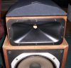
Well I believe this is my first step!

Cab flipped, holes filled in, guide cab on top with grill covering Xover. :scratch2:
(Xover just for affect not actual xover) :)
 

Attachments

  • front_870.JPG
    front_870.JPG
    86 KB · Views: 129
  • close_998.jpg
    close_998.jpg
    118.6 KB · Views: 121
  • top_977.jpg
    top_977.jpg
    97.8 KB · Views: 144
Vertical baffle spacing and null angles

In my view, minimizing edge diffraction of the waveguide is more important than squeezing the last available bit out of center distance.

See my pic @ #813, above, and also some of Jack's baffles. He recesses the waveguide flush.

I'm hoping Wayne will step forward with the answer; from his commercial designs, though, it's apparent he doesn't consider center distance that critical an issue:

http://www.pispeakers.com/catalog/product_info.php/products_id/97

Actually it is one of my highest priorities to space drivers vertically so that the null angles are outside the pattern slightly. The importance how far outside isn't as important as the point that they be outside the pattern in the first place.

If the system design places nulls within the pattern, that's a deal breaker. If that happens, nothing else matters. You can have perfectly flat response and zero diffraction, rarefaction, reflection, distortion, no other anomalies whatsoever on the forward axis and if anti-phase nulls form at narrow vertical angles, it is a non-viable design, in my opinion.

Think about it. Anti-phase nulls form deep notches in the overlap band. The average amplitude through the overlap band at positions near the null angle is reduced only a few decibels but at specific frequencies and locations near the null angles, there are huge spiked dips. So if the angle is narrow, say less than 10 degrees, then you basically have no forward area where response is good.

Geddes Summa, for example, has a round horn that prohibits close vertical spacing between drivers. As a result, the anti-phase nulls start at 7.5 degrees. That's such a narrow angle that the null forms straight in front of the speaker for 12 feet back! It is absolutely imperitive that these speakers be mounted in such a way that they favor upward angles, because on a stand or wall mounting virtually ensures the listener will be treated to deep 10-15dB notches between 1.0kHz and 1.5kHz. No matter how good the rest of its performance is, if you're sitting in a null, response is bad.

I have a lot of respect for Earl Geddes, but until and unless this issue is addressed using an asymmetrical horn with shorter vertical dimension, the narrow null angles impose a serious performance penalty, in my opinion. That is why I do not use or recommend round horns for an application like this.

The best thing about 90x40 and 90x50 horns is you can setup the baffle spacing and crossover so the nulls fall above and below the horn pattern, just outside. It can be right on the edge or 5 to 10 degrees outside. That's a very nice arrangement, because then what you hear as you move up or down outside the pattern is a loss of HF, just what you would expect. You don't hear a weird phasey sounding anomaly like you hear when nulls are placed in the middle of the pattern. You also don't waste HF energy directed at the ceiling and the floor.

 
*sigh*

I was afraid there would be math.

I'll attempt to sum up Wayne with the fewest inaccuracies possible:

HF motor behind LF motor = pattern tilted 'upward'

driver centers farther apart = lower crossover F to achieve flat response forward.
Corrolary: higher crossover freq = closer driver spacing to keep nulls out of forward pattern.

Looking at the example given, and assuming that jackgiff's EWG crossover* meets the criteria of the example, overlapping the EWG rim over the rim of a LA woofer results in an 8" c-to-c distance and about a 50 degree arc between nulls.

* assuming the 1K2 LP and 3K HP = approx 2K1 crossover point
 
So what do we want our spacing to be on this?

In my config with a 12" woofer, I have 12" between woofer and horn centers.
About the best you could do with a 12" woofer is roughly 10" spacing basically.
 
Back
Top Bottom