• The move to the new server is done. There are some software and database maintenance updates in process. This has us passing the hat around to help out. We appreciate any donations. Seriously, even a dollar helps. The payment page may be found here - https://www.audiokarma.org/support.html

Zilch's AK Design Collaborative - Econowave Speaker

The only optimized, documented and "official" crossovers for EWave are listed at the top of the thread. If your components are different, which they are, it's going to be an experiment. I think Russell has had the closest system, in my memory, to what you propose. JBL 2225, EWaveGuide, D220Ti. I am not sure what tweaks he did if any to the EWAVE crossover, or if he tried that combo with the 4Pi x-o. PM him and I'm sure he'll let you know.

I think he did the standard high efficiency crossover, but then he mentions something about the 1.5 version? I don't know what that means.
 
Byrd, there is an original and a "new" version of the 4Pi crossover. If memory serves, the original is 1st order in the LF. The "new" 4Pi is 3rd order top and bottom.

You can build to the "new" but you really need to guestimate adjust for attenuation on the HF side based on you driver efficiency differences particularly if you are not incorporating an L-pad.

If you feel you have the attenuation correct or close, measure (added for measuring guys) or dial in by ear.

If you are building exactly to Wayne's new 4Pi layout, you will use banks of series resistors (R1) and parallel (R2) in the HF. These is for high power applications etc. If you are like me and not running monster power amps at hair parting levels, you can make adjustments at R1 and R2 to get you to maybe a single high wattage resistor per location. This info is also available through Wayne. Varying the R2 resistor(s) from 8-16 Ohm will allow you to fine tune.

It's easy to make changes on the fly if you build using wirenuts or euro connector. Save the "pretty" for after you sort everything out.

RC
 
Wayne's 3Pi crossover is here:

http://audioroundtable.com/forum/index.php?t=msg&&th=12067

Jumper J3 on the eWave PC board is the insertion point for the additional capacitor to run the highpass 3rd order if desired or required.

The Zobel in the lowpass, if used, may be added externally, as well, as I did in eWave 4x, shown in the pic, rear.... :yes:

attachment.php
 
Last edited:
Okay, so I should make the 4pi crossover, and keep the resistors accessible so I can adjust the attenuation? Does it matter I am using the 220ti's and not the BMS?
 
Okay, so I should make the 4pi crossover, and keep the resistors accessible so I can adjust the attenuation? Does it matter I am using the 220ti's and not the BMS?
You mean not the B&C DE250? If so, all bets are off.

Just to recap, you're building with bolt-on D220Ti and the QSC 152i waveguide mated to 2226H woofer?

I will argue that you're not going to get the attenuation correct without measurement capability, and that you should stick with the eWave crossover, which incorporates an L-pad to accomplish this.

The next round of "Flex You Mettle" I will post next week is that compression driver/waveguide combo with the new Dayton 12" pro woofer, which, at least insofar as the highpass filter is concerned, should get you close to optimum.

At this point, I have only done a preliminary trial, which is documented in this thread on DIY audio:

http://www.diyaudio.com/forums/multi-way/169755-what-would-you-do-cabinet.html
 
So... use this with an additional zobel for the 2226Hs?

http://www.audiokarma.org/forums/showthread.php?p=3448405#post3448405
No. That crossover is specific to the combination of drivers and waveguide used in Deluxe, and while it can be built on the eWave PC boards, it is not standard eWave (Parham, Pi-Speaker derivative) topology, whereas the one shown on diyAudio is.

I don't know where the design will end up on "Flex Your Mettle," but I will be making an initial try at it in PCD using eWave topology when initially posting the new round.

This is not about being dense, rather, merely not appreciating that each of these designs varies in detail depending upon what drivers and waveguide are used, and you are considering one which has never before been tried. Generally, eWave looks at the highpass and lowpass independently, gets the highpass for a specific compression driver/waveguide combination firm, and then tailors the lowpass to mate with that. Final optimization of any particular system may require adjustment of the highpass, as well.

We cannot do this for every possible combination, but we have documented a process via which it may be accomplished for any individual one over on Tech Talk, working through an unprecedented eight designs so far this year, with several more in the works.... :yes:
 
Last edited:
Okay, looks like I should shell out for the B&C DE250s then.
Not necessarily. Give me another week or two to get this done. From what I heard in the preliminary trial, the Seleniums work credibly well with the QSC waveguide.... :thmbsp:
 
Wayne's 3Pi crossover is here:

http://audioroundtable.com/forum/index.php?t=msg&&th=12067

Jumper J3 on the eWave PC board is the insertion point for the additional capacitor to run the highpass 3rd order if desired or required.

The Zobel in the lowpass, if used, may be added externally, as well, as I did in eWave 4x, shown in the pic, rear.... :yes:

attachment.php

I'm going to have to get caught up on the"Flex your meddle" thread, I'm finally reaching the end of the Pass projects and can redirect funds back to the measuring system. Pre is done, power amp is 3 thermistors short of being fired up, pearl boards are on the way. So at least I can see a chance to get back on measurment track. I've been feeling around blind long enough.

Russellc
 
Last edited:
Okay, looks like I should shell out for the B&C DE250s then.

They are nice, but if you have the bolt on 220ti, use that. Use the crossover Zilch works out for it, then go over to lansing heritage forums and look at crossovers that use the 2226h and get zobel ideas, or see what Wayne uses on his version of the 4 pi that uses that driver. Add it to the LP, and I'm sure it will be listenable. Then tweaking and measuring will be necessary to dial it in. I used the standard
Deluxe crossover and added the zobel from JBL 4430, which uses the same driver I am currently using, the 2235H. Worked out surprising well for throw together, measurment capability will be along in a quick.....I've said that for a while now.....:yes:

Russellc
 
Crossovers for DI-matched two-way speakers

Just a point of clarification:

The basic crossover topologies of most (all) of the speakers discussed in this thread are similar in terms of transfer function and of basic design. There are definitely differences, most of which are intended to get phase right to set the position of the forward lobe, balancing the variables of midwoofer and driver/horn reactance and driver position with crossover phase to ultimately set the position of the forward lobe and vertical nulls. But in general, we're talking about a single type of crossover, a two-way crossover that matches directivity in the crossover region and has top-octave compansation for (the mass-rolloff of) a compression driver on a CD horn.

There are differences as to the slope of the core splitter filters (1st-order, 2nd-order, 3rd-order) but even those are often chosen at least partially to set phase. The rolloff slope is often chosen to hit a design goal with respect to excursion, especially for the compression driver when used on a horn that will limit the excursion at high frequencies but that will unload at some low frequency limit, allowing the compression driver to move much further than it should, hence the need for rapid rolloff down low.

Still, in basic function, they all do the same thing (or should) and ultimately have the same transfer function, beyond the slope in the crossover region. The top-octave will always droop at a consistent 1st-order rate, simple physics, mass-rolloff has this slope. So a first-order conjugate is required. Some drivers may have extra breakup up high, so that can sort of make them a little hotter. Midwoofers may have breakup, making the low-pass need a notch filter or faster rolloff or something. Those are the kinds of details that cause the differences. But the basic design is the same.

When I first started making speakers like this, I experiemented with several crossover styles, several core splitters with different slopes and frequencies and several "auxiliary filters" such as notch filters and the like. I've used first-order filters through fourth-order filters and usually in new designs, I investigate all of them. In my crossover document, I show several basic crossovers, including a first-order using notch filters, another first-order with series/parallel attenuator/damping padding, a second-order, a third-order and mixed slope asymmentrical filters.

The first-order crossover shown in my crossover document (without a notch filter) is very much like what you guys call a "Deluxe" or 5 component crossover. The padding resistor values are much smaller in a circuit like that than they are in the higher-order crossovers, they have to be to get damping right for the transfer function needed. The crossover document also shows second and third-order filters, with component values appropriate for those kinds of networks. They allow more versatility in damping/peaking near crossover, but of course, require more components. In the end, you can read about each of those networks and what I thought about each of them from my little study/demonstration document, below. But also, ultimately, they all serve the same purpose and have the same basic topology, at least to my mind.

 
Thank you, Wayne for your many and ongoing contributions to our projects. :thmbsp:

Jack always had a more thorough understanding of the filters than me, as is evidenced by how well his implementation(s) of your design concepts have stood up over these several years. It's only via PCD that I am able to manipulate the variables with confidence, and much of that is just me getting the attenuation and damping correct for various driver/waveguide combinations.

Very few designer/builders understand the concept of "setting the forward axis," and followers of this thread have had the dubious pleasure of watching me struggle to get a handle on it empirically. Again, modeling software like PCD is a tool essential to the task of adjusting frequencies, slopes, notches, and conjugates in this design optimization process. Your Vertical Nulls video was the impetus for my digging deeper into all of that, and the results have been most rewarding in the ultimate performance.

[I could never have imagined how stunning a pair of roadkill AR4x could be upgraded to sound via e'Waving them.... :) ]

http://www.classicspeakerpages.net/IP.Board/index.php?showtopic=5985
 
Last edited:
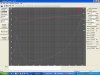
Hi All, well, it looks like I will be building a more standard eWave. I did have no-name compression drivers and the QSC, but Ross, bless his heart, is giving me a pair of 210s and Pyle horns. So the question is how will the woofer work in the cabs I have....this is were I need help. Below is a pic of the Woofer Tester screen shot for the Credence 12" woofer I have and the Infinity cabs are (with the horn installed) approx. 1.25 cu ft.

I was wondering if some one can put the woofer data into a box program and see where it ends up ported and unported. Cheers and thanks.
 

Attachments

  • Creadance woofers WT3.jpg
    Creadance woofers WT3.jpg
    68.4 KB · Views: 44
AH, I see that now Z. I'll just put them in the box and see what comes out. I also have to figure out the SPL so I can figure out what xover to use. I am not sure how to go about doing that if I don't have any equiptment. Any suggestions?
 
Back
Top Bottom