• The move to the new server is done. There are some software and database maintenance updates in process. This has us passing the hat around to help out. We appreciate any donations. Seriously, even a dollar helps. The payment page may be found here - https://www.audiokarma.org/support.html

AK Design Collaborative - Insubnia

See the VolvoTreter link above. There's a tapped-horn design tool in his downloads.

If these work worth a whit, there's only one driver per and with a low power plate amp (only 30W required, looks like), they could come in at ~$150 complete.

I'm not a bass horn guy, but there's others like yourself that know the ropes with these here, so I'm confident we can make this happen.... :thmbsp:

Are you talking $150 per subwoofer? Do you plan to use at least 2 per system?
 
Mike,

Thanks for posting driver measurements....I'll run the numbers again for my 1st iteration with them....Ever measure the TB W8-740P? It is my candidate for the 20Hz iteration of Insubnia...and on sale...

JSS

I have the W8-740Cs, which are similar, but not exact.

Never bought any W8-740Ps.
 
Are you talking $150 per subwoofer? Do you plan to use at least 2 per system?

A lot depends on the driver and amp ultimately used. The W6-1139SI drivers are under $30 each when on sale, though they are normally $50. Different drivers = different costs. I have a few I like that are cheaper, and a lot I like that are more expensive.

There are decent amps for $35 plus shipping, but they require some time with a soldering iron to replace some resistors. Add in a realistic $50 for the wood, construction and finishing supplies, and other incidentals, and you're at $150 per sub, though you could presumably add slave subs for closer to $100/per.
 
Are you talking $150 per subwoofer? Do you plan to use at least 2 per system?
Yes, including the plate amp, which would be optional. Some might run multiples on a separate amp.

I believe there are many Indignia builders who would just use a single to augment them, or with Mindignias for an even smaller system, as well as others building the complete Karma Indignia Theater.... :yes:
 
We looked at VolvoTreter's double-folded 38 Hz tapped horn, which is just under 2 cuft. external, and suggested that was sufficiently compact. 3 cuft. is 24" x 24" x 9", and that's certainly within the realm of what we were earlier considering with our bandpass approach. We probably want to pay attention to dimensions from the perspective of economical use of materials, as well. Many builders will be purchasing MDF or birch ply solely for constructing this project.

I believe we have agreed that 30 Hz is an acceptable target, but I doubt anyone would object to it playing to 25 Hz, instead. This is intended to mate with and augment Karma Indignias, an earlier successful collaborative project here, which play with some authority down to 40 Hz. They do have their limits down there, though, admittedly unknown. I believe Max is running the calcs on those for us. The plan is to include a plate amp in the design, which could incorporate highpass filters for both sub and mains, though nobody has looked at that aspect in detail.

We don't aspire to THX spec SPL with this compact system, but as we proved with Indignia, I believe we can easily surpass the performance of similar commercial offerings. One driver per box would be preferred, and those who so desire can build multiple inexpensive Insubnias. Typical deployment would be at floor and wall boundaries, i.e., 1-pi, corner placement optional for those who can take advantage of that for additional SPL....

2-3 cu ft? That's huge? Why use a small driver when a 12 will work well in that? This 12" vented as a B6 alignment tuned to 20-25 Hz in about 2.5 cu ft should be impressive:
http://www.parts-express.com/pe/showdetl.cfm?Partnumber=295-490

However, for 20-30 bucks more you can get a much better driver. That one being efficient means you'd not need a lot of power, so save on the plate amp also.
 
2-3 cu ft? That's huge? Why use a small driver when a 12 will work well in that?
I'm citing external dimensions, Pete; the net will be smaller.

Let's see what Max and Mike come up with here.... :yes:
 
Last edited:
2-3 cu ft? That's huge? Why use a small driver when a 12 will work well in that? This 12" vented as a B6 alignment tuned to 20-25 Hz in about 2.5 cu ft should be impressive:
http://www.parts-express.com/pe/showdetl.cfm?Partnumber=295-490

However, for 20-30 bucks more you can get a much better driver. That one being efficient means you'd not need a lot of power, so save on the plate amp also.

To each their own. No offense meant. There are lots of ways to skin this cat.
 
Last edited:
Take a Dayton Classic 10" (http://www.parts-express.com/pe/showdetl.cfm?Partnumber=295-202) in a 2 cuft box, tuned to 28Hz and add a 70W plate amp (http://www.parts-express.com/pe/showdetl.cfm?Partnumber=300-784) and you'll get an f3 of 29Hz, an f6 around 25Hz, and an output of 106dB. Total for speaker and amp would be <$140. If a group buy happened it would probably be <$100.

It's a simple build, although it might need a snorkel port depending on what dimensions you go with. Could also be built with a shelf/slot port to make things easier.
 
To each their own. No offense meant. There are lots of ways to skin this cat.

I'm certainly open to new ideas but I like to see them compared to some obvious solutions, such as the one that I suggested. I'm curious to see the alternatives that people come up with - so please carry on ...
 
OK,

Reworked the OD FLH Insubnia, with lilmike's measurements of the TB W6-1139SI driver...

Layout:

Insubnia%20Measured%20W6%2030Hz.jpg


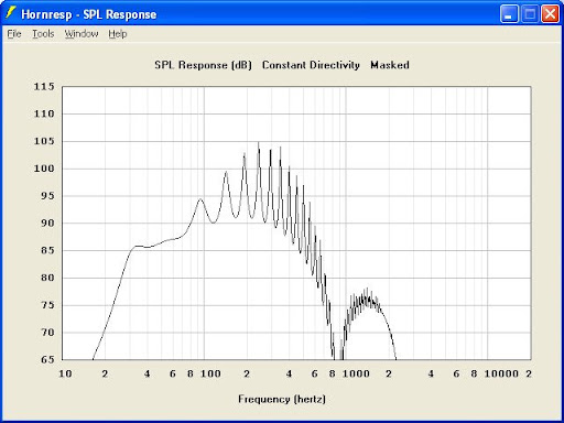
Hornresp sim, 2V, 2Pi:

Insubnia%20v2.png.jpg


Final dims, with 3/8" MDF throughout: 20.75"x20.75"x9.5"

Corner loaded, Xmax limited at 25Hz, 15V in, gets you 115dB from 30Hz on up according to hornresp...so it can be assumed that you may be able to get a clean 105dB from it when corner loaded...highpass it, and you can get a few more dBs....the driver is on it's way....so I'll be making sawdust soon...

JSS
 
Last edited:
Wow - 3/8"?

I can barely get a brad nail into 1/2" material. Are you planning on routing the side panels or butt-joining the cabinet together?
 
probably butt-joins, I am pretty good with a brad gun...it would take a little bit of time to generate a template for routing the sides...but it is a good idea.

Main reason I am very interested in this project is I want to build the KIT for a friend who is getting his doctorate this year.....he isn't an spl or bass-freak, and I figured I could make the KIT look very nice...and mount the speakers on the walls, out of reach for the 1-year-old he has...

Have you had time to work up a tapped horn solution?

JSS
 
Pocket screws would work for 1/2. Then you would not see any screws at all. The one problem is that would add to the cost of the project. Small pocket screw jigs are about $30-$50. You can get one called "General" at Home Depot. You can get the Kreg Jig at Lowe's. The Kreg is my fav. Very good tool.:thmbsp:

BTW It would probably work for 3/8 but screws would have to be 5/8". could probably adjust for 3/4" screws tho I have never tried.

Then there's always cleats.
 
Last edited:
Are there calculations that will give the exact angles for all those interior joints?

I dont think that would be necessary. Once the size of the unit is known, measurment would allow you to place the first interior board (by messuring top to bottom , side to side ). Notice the illustration shows how t he individual boards are butted up against each other? By placing the next board ( of known length ) in position against the first, you would need to know the distance from its end to the edge of the bottom piece your attaching it to. ( and of course the length of each board) And continue in that fashion until finished. Mount driver and wiring, electronics etc. Then put the top, (Identical in size to the bottom piece) and its done.

You would need to know the dimensions of the "bottom" piece. The top to bottom and side to side measurements to place the first board, and its dimension. Then the measurement from the end of each successive board to the side wall its against.
since this measurment is taken from the tip of the successive board, the angle would be set.

PS The "first interior board" didnt get explained, in the illustration put your pointer on the outside board at the top. If you slide straight down, the first interior board or panel you hit is the one I'm talking about attaching first.

Russellc
 
Last edited:
probably butt-joins, I am pretty good with a brad gun...it would take a little bit of time to generate a template for routing the sides...but it is a good idea.

Main reason I am very interested in this project is I want to build the KIT for a friend who is getting his doctorate this year.....he isn't an spl or bass-freak, and I figured I could make the KIT look very nice...and mount the speakers on the walls, out of reach for the 1-year-old he has...

Have you had time to work up a tapped horn solution?

JSS

Got a sim or two that have some potential, but the impulse is not clean enough yet and I still have to work on the damping a bit. Definitely need to spend some more time polishing the models up, then give it a quick sanity check to make sure it can be built. Unfortunately, I really have not had a lot of time to work on it, I hope to have a few spare minutes today or tomorrow. Size is just a touch bigger when compared to yours, but the efficiency is a bit higher and it will reach 25 Hz without sitting in a corner. I think that 3/8 internal dividers would be OK for low levels, but since I'm not planning on any bracing, I'll probably suggest 1/2 birch ply or MDF.
 
I dont think that would be necessary. Once the size of the unit is known, measurment would allow you to place the first interior board (by messuring top to bottom , side to side ). Notice the illustration shows how t he individual boards are butted up against each other? By placing the next board ( of known length ) in position against the first, you would need to know the distance from its end to the edge of the bottom piece your attaching it to. ( and of course the length of each board) And continue in that fashion until finished. Mount driver and wiring, electronics etc. Then put the top, (Identical in size to the bottom piece) and its done.

You would need to know the dimensions of the "bottom" piece. The top to bottom and side to side measurements to place the first board, and its dimension. Then the measurement from the end of each successive board to the side wall its against.
since this measurment is taken from the tip of the successive board, the angle would be set.

PS The "first interior board" didnt get explained, in the illustration put your pointer on the outside board at the top. If you slide straight down, the first interior board or panel you hit is the one I'm talking about attaching first.

Russellc

The way I typically build front-loaded horns is to accurately lay out the entire fold pattern on the side of the cabinet, then attach the boards working from the center out. The first boards installed are usually the baffle or the side of the back chamber that the baffle attaches to.

Tapped horns are similar, except the first board is the baffle. I use brad nails or screws, as appropriate, and polyurethane construction adhesive. Clamps and squares help a lot.
 
I dont think that would be necessary. Once the size of the unit is known, measurment would allow you to place the first interior board (by messuring top to bottom , side to side ). Notice the illustration shows how t he individual boards are butted up against each other? By placing the next board ( of known length ) in position against the first, you would need to know the distance from its end to the edge of the bottom piece your attaching it to. ( and of course the length of each board) And continue in that fashion until finished. Mount driver and wiring, electronics etc. Then put the top, (Identical in size to the bottom piece) and its done.

You would need to know the dimensions of the "bottom" piece. The top to bottom and side to side measurements to place the first board, and its dimension. Then the measurement from the end of each successive board to the side wall its against.
since this measurment is taken from the tip of the successive board, the angle would be set.

PS The "first interior board" didnt get explained, in the illustration put your pointer on the outside board at the top. If you slide straight down, the first interior board or panel you hit is the one I'm talking about attaching first.

Russellc

As I see this design, the width of the passageway is tapered, that is, it gets increasingly wider as it spirals out from the center. That is evidenced by the fact that the central 'box' is twisted in relation to the outer case. In order to do this, each of those right angle joints have to be slightly greater than 90deg, except for the first joints on the central box and the outer case.
If only the length of each panel is increased, the sides of the spiral would all be parallel to the outer case. Each section would be wider than the last, but there wouldn't be a gradual taper as shown in the diagram. As I understand the theory, that is the purpose of the design.
Granted, the angle would only be a degree or three, and caulk might be sufficient, but considering that this will be used for bass, rigidity should be important, which comes with solid joinery.
Maybe I'm just seeing this wrong... :scratch2:
 
Back
Top Bottom