• The move to the new server is done. There are some software and database maintenance updates in process. This has us passing the hat around to help out. We appreciate any donations. Seriously, even a dollar helps. The payment page may be found here - https://www.audiokarma.org/support.html

AU-717 relay replacement

bzb882

AK Subscriber
Subscriber
Does anyone know if Digikey relay Z2634-ND (Mfg #MY4-02-DC24) is the correct replacement? I has two extra rows of prongs down the center. If it is correct, what do I do with the extra prongs?
 
Register to hide this ad
What's a good way of cutting off those two middle rows of pins? There's very little room between them and the outer two rows that need to stay,
 
That is not the correct relay. Use omron My2-02 24v dc....I have used this in many AU-717's.
 
I have some spare relays and they are marked MY4-02-DC24 - they have 2 rows of pins i.e. NC & NO next to each other, and the wiper row spaced between the coil contacts and the NC/NO contact row.

Sooooo, what is the difference between MY2-02-DC24 and MY4-02-DC24 ?

EDIT: update
The MY2 has only 2 contacts whereas the MY4 has 4 - these 4 contacts are joined together on the '717 for extra current capability/lower contact resistance - but I think not on the '517 ? - need clarification ?

So, I think the MY2 is for the '517 and the MY4 is for the '717 - but you can use either. (just not the MY2 for the '717)
 
Last edited:
The MY4 is the correct one. The MY2 can be used, but you lose current-carrying capacity compared to the MY4. The center pins on the MY4 should not be trimmed off*, or the resulting current capacity is reduced even further. The holes are there, the foil pads are there...use them!

*(I can't remember if all the holes are there or not in the PC board for the outer row of 'NC' pins. They aren't used in any event, so trim the ones you need in order to fit the relay onto the PC board, but under no circumstances should you trim any pins from anywhere except this outer row of 'NC' pins.)
 
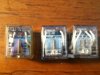
I have the original relays from the 717's i've done and I dug one out to compare. Pic attached. The original is on the left...the MY 2 next and the MY4 on the right. So EW you are saying that the MY4 is an upgrade to the original with a higher current capacity?
 

Attachments

  • 008.jpg
    008.jpg
    68.6 KB · Views: 81
  • 009.jpg
    009.jpg
    73 KB · Views: 98
Yep.

No reason in the world why you can't use an MY4 in the 517 & 717. It's not a huge jump in capacity (the MY2 is 5A per contact [10A total], and the MY4 is 3A per contact [12A total], however, the carry current is much higher), but anything is welcome.
 
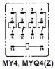
I checked, all the holes are there except for pins 2 and 3. In Zekeman's pic above, that's the bottom row (reading left to right 4 3 2 1, so the middle two pins on the bottom row). There's continuity between 2 and 10 and also from 3 to 11 (middle two pins on the top row of 4). According to the diagram on the top of the relay, that drops down to the middle row (6 and 7, middle pins on the middle row of 4) when energized. So clip off pins 2 and 3 and go with the MY4 relay?
 
Correction, from the diagram, when the relay is energized, there's continuity between 6 and 10 and then 7 and 11,
 
This ain't rocket science...pins 1 through 4 aren't used at all (there may be holes in the PC board, but there are NO foil traces to these pins and thus nothing to solder to). These are the 'NC' pins, the ones making contact with the 'common' contacts (9 through 12) when the relay is at rest. My manual suggests that the PC board lacks holes for pins 2 and 3. I don't know if that's accurate, as I can't remember. If the holes are only there for 1 and 4, then clip off 2 and 3 and solder it up.

When engaged, 5 & 9, 6 & 10, 7 & 11, and 6 & 12 are all connected.

 

Attachments

  • MY4_Pinout.jpg
    MY4_Pinout.jpg
    23 KB · Views: 39
Back
Top Bottom