Follow along with the video below to see how to install our site as a web app on your home screen.
Note: This feature may not be available in some browsers.
The move to the new server is done. There are some software and database maintenance updates in process. This has us passing the hat around to help out. We appreciate any donations. Seriously, even a dollar helps. The payment page may be found here - https://www.audiokarma.org/support.html
I’ve noticed that amplifiers that use voltage doublers don’t usually have filter capacitors directly after the doubler circuit on B1. Are the capacitors in the voltage doubler also used for filtering?
Some do use a cap across the whole thing, some don't. Just depends on the amp. Most don't use chokes but that does help a lot. I suspect its a price point thing, the better the amp the better the filtering.
but yes the doubler caps do serve as the first filter, but keep in mind it ends up at half the value so a pair of 100uf in series is only 50uf across the whole line.
You can, it won't hurt the noise level of the power supply but most of the noise at that first tap will be cancelled in the output stage. I'm assuming its push-pull at least. Noise there goes in common mode so it cancels. A choke or a cap would certainly improve that but lots of manufacturers rely on the noise rejection thing to skimp on power supply filtering. Same reason most bias supplies are pretty dirty.
The tap at the mid point is half voltage, but its also half-wave rectified so its pretty noisy. Thats why the choke is there. My big Bogens run a voltage doubler and the mid tap is run through a choke before it goes to the screens for the same reason. I'm guessing that feeds the tuner stuff? Only reason that supply needs to be somewhat clean is you'll get hum modulation in the tuner circuitry if the supply is too noisy. If it does go to some audio part then it just has to be clean because noise will be amplified.
Effective capacitance for purposes of ripple filtering is actually 1/4 the value. This is because the two caps are in series, as you pointed out, and in addition, ripple current in each cap is 60Hz, not 120Hz. So, the Xc of a single 50uF capacitor at 120Hz will require two 200uF caps in series in the doubler for the same effective ripple filtering. Amplifier decoupling as reservoir caps in series (20Hz - 20kHz) follows the one-half rule you described.
hm yeah fair point. I've bumped the value on doubler caps more than a few times just to knock some noise out of it. Never did the math, but it makes sense. A lot of these things just don't have good filtering, especially when there isn't one across the entire B+ supply.
Not really. The 60 Hz ripple component on the two series capacitors is of the opposite polarity, so cancels, leaving 120 Hz in the output. Effectively the same as a bridge with twice the input voltage. The capacitors do need a higher current rating than a bridge, though, as ESR is about 10-15% higher at 60 Hz than 120.
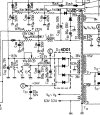
The supply might perform better if the two doubler caps C201 and C202 were about 220uF. However, the benefit is dependent in part on how the output stage tubes are biased. The closer they are to Class A, the less subsonic energy there will be. This is often referred to as sag, but it's a frequency that can be decoupled, just like any other.
Not really. The 60 Hz ripple component on the two series capacitors is of the opposite polarity, so cancels, leaving 120 Hz in the output. Effectively the same as a bridge with twice the input voltage. The capacitors do need a higher current rating than a bridge, though, as ESR is about 10-15% higher at 60 Hz than 120.
Thanks for this, and you're correct. I have some difficulty envisioning the effect of the 180 phase shift, but SPICE confirms it. The ripple content of a doubler with two 50uF caps is the same as a FWB with a single 25uF cap.