
Thunderbox
Super Member
Does anyone have a wiring diagram for an Empire 598 Turntable. These are like hens teeth. Motor doesn't run.



There’s an owner’s manual but not a service manual.Is it in the owner's manual, available on vinylengine?

Is it in the owner's manual, available on vinylengine?
Yes but there are 3 wires going to the motor rather than the normal 2 wires that is why I would like a diagram.There's not much to it. Just a switch, a cap, the motor, and a light bulb.
Got power to the motor when it's switched on?
Yes but there are 3 wires going to the motor rather than the normal 2 wires that is why I would like a diagram.
Which one there are 3 and all different colors. That is why I would like a diagram. They covered all the places where a connection is made so you can't just follow the wires from the source plug.One is just a ground.
Apparently there are 2 capacitors. That is why I need a diagram.There's not much to it. Just a switch, a cap, the motor, and a light bulb.
Got power to the motor when it's switched on?
Which one there are 3 and all different colors. That is why I would like a diagram. They covered all the places where a connection is made so you can't just follow the wires from the source plug.
Yes but there are 3 wires going to the motor rather than the normal 2 wires that is why I would like a diagram.
Apparently there are 2 capacitors. That is why I need a diagram.

Empire used 3-phase Papst motors in their turntables. I don't know if the stator windings are arranged in a wye or delta configuration but you should see equal winding resistance across any two of the three motor wires.
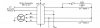
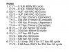
Here is the wiring diagram for the Empire 698 which may or may not be similar to the 598.
View attachment 2030677
View attachment 2030678
It probably is if the power light is neon. In the 698, the power indicator is an LED which is powered from lower voltage DC.Maybe power for the light?
It probably is if the power light is neon. In the 698, the power indicator is an LED which is powered from lower voltage DC.
Thanks for the information. The motors on both the 698 and the 598 are the same motor.Sure looks similar.
C1 is the cap across the switch.
C2 is the run capacitor
I've got blue brown and violet leads coming out of my motor.
If the coding is the same, then blue is the common wire.
Brown is the switched 120V lead.
Violet connects to the 4uf run capacitor [3.6uf on my TT].
The run cap is fed by a black wire on mine.
But there's a second black wire connected as well.
Maybe power for the light?
I'm finding it very awkward to get a good look without pulling the TT from the system.
Space and clearance are tight here. I don't usually move stuff around unless I really have to.
Thanks for the information. The diagram from the 698 is probably the same but you have to add the light into the diagram no big deal on that. I am very disappointed with the lack of quality in the wiring of this turntable. I think I will rewire the entire set up. Thank you.Sure looks similar.
C1 is the cap across the switch.
C2 is the run capacitor
I've got blue brown and violet leads coming out of my motor.
If the coding is the same, then blue is the common wire.
Brown is the switched 120V lead.
Violet connects to the 4uf run capacitor [3.6uf on my TT].
The run cap is fed by a black wire on mine.
But there's a second black wire connected as well.
Maybe power for the light?
I'm finding it very awkward to get a good look without pulling the TT from the system.
Space and clearance are tight here. I don't usually move stuff around unless I really have to.


you can just make out that choke looking thing


