• The move to the new server is done. There are some software and database maintenance updates in process. This has us passing the hat around to help out. We appreciate any donations. Seriously, even a dollar helps. The payment page may be found here - https://www.audiokarma.org/support.html

EPI 601's

New poly caps will return the sound to what they were shooting for back in 1971. They just didn't want to cut into their profits so they passed on coils and used electrolytic caps, which I've learned here fail over time because they are NOT constantly exposed to current. Intermittent use is not detrimental to the poly cap, and therefore your $ and time investment will not be wasted. These speakers are not going to fix themselves. By your pics, it looks like the speakers were installed with their own color coded wires, and the crossovers came with those same color coded wires and in final assembly, a wire nut was used to complete the circuit. Got to keep it simple for working inside the cab even back then. I would be tempted to eliminate that set up and go for heavier wire and no wire nut joint but one continuous line from speaker terminal to crossover. The wires might be a little longer so you could work outside the cab, but without the shaky twist joint to restrict current. Just an opinion.
 
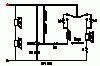
I just opened up the the working speaker and drew a diagram off all the connections inside with the cap, resistors, pot, and switch. I tested the pot and it range from 26 ohms to 8 ohms on both speakers. What is the best way to test the switch?
 
Your potentiometer numbers are good. To test the switch, first consider your crossover:

attachment.php


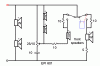
Note that you have a double pole double throw (dpdt) switch in the circuit. Two of the poles are common - trace the top line all the way to the right and down into the switch. Hook one meter lead to the switch at this point. Then, read across the switch to one of the poles on the other side:

attachment.php


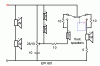
With the meter set to read continuity, or ohms, flip the switch back and forth a few times. You should see the reading go from open (OL) to closed (0 ohms). Leaving the first lead hooked to the common point, move the other lead to the other pole:

attachment.php


Again, flip the switch back and forth, observing the readings. Repeat for the other pole.

attachment.php


attachment.php
 

Attachments

  • epi-601.gif
    epi-601.gif
    5.3 KB · Views: 71
  • epi-601a.GIF
    epi-601a.GIF
    6.7 KB · Views: 70
  • epi-601b.GIF
    epi-601b.GIF
    6.6 KB · Views: 73
  • epi-601c.GIF
    epi-601c.GIF
    6.7 KB · Views: 69
  • epi-601d.GIF
    epi-601d.GIF
    6.6 KB · Views: 70
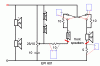
While you are in there, you should test all of your resistors:

attachment.php


With the dpdt switch in the red position, you should be able to test the top two 10 ohm resistors by placing the leads across the resistors, one at a time. If you will disconnect the front woofer and the front tweeter as indicated by the heavy red lines, you should be able to measure directly across the other two resistors. You may be able to jump across these two resistors, but do so at low volumes - the speakers will be unusually loud and the voice coils will be subject to higher than usual current.
 

Attachments

  • epi-601e.GIF
    epi-601e.GIF
    7.6 KB · Views: 71
Thanks for the great info....After i get home from work I will perform those measurements.

The OP was the main speakers not working so I would be interested to see if this switch works.

Off to find out if we are having a boy or a girl....I'd rather be surprised :P
 
Thanks! Its a girl!! I already have a daughter so another one pretty much assures me I will lose very battle in the house haha!!
 
Ok, the switch works as it does on high read 0 ohms, off read 38 ohms, and normal read like 11 or something...haha i didn't right it down. The resistors for the switch are each measuring 10 ohms...I need to recheck the 5 ohm resistor but I think its reading OL...but the working speaker has the same reading so i need to make sure i am doing it right.
 
Ok, the switch works as it does on high read 0 ohms, off read 38 ohms, and normal read like 11 or something...

This is strange. According to the schematic, your switch should have only two positions, but from your post, the switch actually has three positions, right?

BTW, congrats on the great news!
 
yep, high, off, and normal.

I get 10 ohms for the resistor under the pot...the other 2 are 10 as well. i get OL for the 5 ohm...? but...i also get OL for the 5 ohm on the working speaker....

I made a diagram of the working speaker and hooked the broken one back up....its works just like whne i got the speaker 4 of the 6 speakers working...the 2 fronts being dead (but when I plug them in where the other woofers are they work so its not the actual woofer.) also the tweets need to have the volume cranked to barely hear them...with the woofers disco'd again so i dont go deaf. :)
 
I will scan my diagram and post as well. This shows where the actual wires go....kinda of confusing but it helped me wire the dismantled speaker as I took it apart and had no clue how t put it back haha! Thanks again for all yor help!
 
If you are measuring across the 5 ohm resistor and measure open, that could explain the front woofer part of your problems. According to the crossover schematic, there are three 10 ohm resistors in the crossover. You said you tested the two near the switch. Did you measure the third 10 ohm resistor near the bottom of the schematic?
 
Does off engage both resistors?
Well, the three position switch doesn't agree with the schematic, so I don't know for sure. My guess is that off is in a null position that effectively disconnects the front speakers, leaving the two rear woofers and tweeters on.
 
If you are measuring across the 5 ohm resistor and measure open, that could explain the front woofer part of your problems. According to the crossover schematic, there are three 10 ohm resistors in the crossover. You said you tested the two near the switch. Did you measure the third 10 ohm resistor near the bottom of the schematic?

Its weird because the 5 ohm resistor reads OL on the working speaker.

Yes i did measure all 3 10 ohm resistors and they all measured 10.
 
So basically order 5 ohm resistors and 10uF poly caps....swap them out and see what happens. i may be able to do this without taking out the crossover as i have learned the crossover by heart and now where every wire and component goes.

Which resistors from parts-express? just a standard 5 ohm 10W 10%?
 
I have some 602s which are essentially identical. I rebuilt the crossovers without the L-pads. Remarkable sound indeed. Keep at them, it is worth it.
 
What is an L-Pad? I will shortly. I forgot the drawing at work. I will draw in the 3rd 10 ohm resistor as well as I did nopt see it until last night.
 
Back
Top Bottom