• The move to the new server is done. There are some software and database maintenance updates in process. This has us passing the hat around to help out. We appreciate any donations. Seriously, even a dollar helps. The payment page may be found here - https://www.audiokarma.org/support.html
*b-h curve math and some basic examples, chart with linear vs saturation regions

*62 pages of engineering nerd bliss, page 5 section 1.2 has a nice material comparison chart (numbers)

would have been nice if the out-txf was uncovered to show off its racing stripe even though peerless uses different cores with the same model number. the diyaudio link above shows a half-circle notch in the laminations on one side, no such variance exists with the bench txf.
 
half-circle notch in the laminations on one side

That is just a material supply variation. I have a pair of modern OPTs with the same part number, one has that notch, the other doesn't. I don't like how it impacts cosmetics, but I don't believe it affects performance in any meaningful way.
 
for those who want to venture down a somewhat more advanced power magnetics rabbit hole:

Screenshot 2026-08-19 at 14-32-59 It's Happening - Europe is Building an Impossible Fusion Rea...png
www.youtube.com/watch?v=bPUAKW1Dyek

Screenshot 2026-08-19 at 14-35-58 The World's First Grid Connected Fusion Plant - Nuclear Engi...png
www.youtube.com/watch?v=nt4rZgndOoE

**it does help to hear from someone who actually works in the industry vs going solely off of what an informative ph.d venture capitalist says.**

and now back to vintage audio gear output power magnetics (impedance matching edition). best not to think about dark matter, black holes, event horizon and next months credit card bill...
 
heathkit w5m - 133.jpg
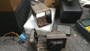
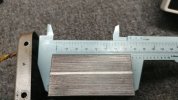
definitely a physically small package and footprint

heathkit w5m - 135.jpg
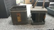
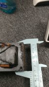
its nice that the cosmetic container survived the extraction process

heathkit w5m - 136.jpg
the slightly oversized container must have been a dual strategy, increase the chances of using slightly different txf sizes to some extent.

out-txf capacitor findings/measurements coming up next.
 
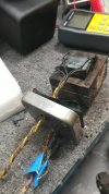
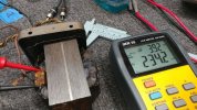
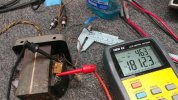
measuring across each txf cap (1 of 2)

heathkit w5m - a134.jpg
100hz= 234.2nf esr= 3.92k

each cap is across anode/plate and screen grid/g2 taps.
 
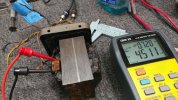
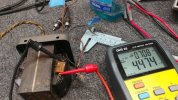
heathkit w5m - a136.jpg
10khz= 4.51nf esr= 720r

these LCR measurements are obviously with the cap in circuit. all wires separated nothing shorted in the background, primary and secondary.
 
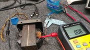
heathkit w5m - a137.jpg
measuring from anode/plate of the good side to one side of the cap. verifying which tube half-tap is being measured, ct isolated for all measurements as well.
 
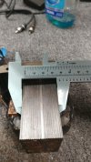
so 1 1/2 x 2 1/2 x 3 inches? Same as the TA-600 so far as I can tell. The TA-600 runs 7189 tubes and makes under 20 per channel. I don't have the 800 iron in front of me to measure but its pretty close to the same size as the 600 transformers despite being a 7591 amp and doing closer to 25 per channel.
 
the other side (cap 2 of 2), that measures high between ct and anode or g2.

heathkit w5m - a138.jpg
100hz= 217nf
esr= 3.85k
 
Last edited:
Thanks for sharing all this information!

measuring across each txf cap (1 of 2)
Does this mean each transformer has two caps?

each cap is across anode/plate and screen grid/g2 taps.
So, there is a capacitor between anode no.1 wire and screen grid tap 1 and another capacitor between anode 2 and screen grid 2?
I don’t see the second capacitor. Perhaps I misunderstood what you wrote. Could you clarify please.

I’m also puzzled by the strongly different capacitances you measure at different test frequencies. I don’t know if this is expected as I have not played with a capacitance tester at different frequencies.
 
I don’t see the second capacitor
i edited post #313 to clarify.

capacitor between anode no.1 wire and screen grid tap 1 and another capacitor between anode 2 and screen grid 2?
correct, thats what the basic measurements seem to point towards.

measuring the cap in circuit with the txf coils might skew a few things, small capacitance with a large overall inductance.
 
since amp #2 is an unknown timeline at this point, i will try to wrap things up and declare v1.0 without any more fine tuning even though it would be beneficial.

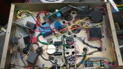
heathkit w5m - 137.jpg
one last view of the v1.0 layout before the chassis panel is installed

updated schematics and closing thoughts about various loose ends will be posted soon. overall this proof of concept renovation has a few too many complexities. some are needed to combat over-voltage conditions that stress out components a little too much.

the 16309 deep dive shows how unique and possibly fine tuned it is, anode/g2 caps plus nickel laminations. which adds to the vintage value of a 1st edition w-5m. staying below 20w output and reducing amplitude of frequencies below 30hz would be a good idea to improve out-txf longevity.

using 16309 based mono blocks for highs, mids and upper bass (around 100hz) might be ideal and then use a low cost high output (100-200w) solid-state amp for the bass/dynamics heavy lifting. a 2.2 system consisting of bookshelf ribbon/heil tweeter plus a decent mid woofer and then a pair of 12s or 15s for over-kill dynamic potential. the bose 802 experiment in season-2 might be of value, x32 4.5inch drivers for quick bass and a physically small amp.

perhaps a simple heat shield, for the out-txf, to reflect/deflect/insulate from getting cooked by the output tubes would also help.

too many ideas... for those familiar with computer programming jargon "feature creep" would be applicable.

en.wikipedia.org/wiki/Feature_creep

userjot.com/blog/feature-creep
 
Back
Top Bottom