

You are using an out of date browser. It may not display this or other websites correctly.
You should upgrade or use an alternative browser.
You should upgrade or use an alternative browser.

carlman14
Member
I've been messing around with the IBBA trying to get the 7591's running correctly, and I'm having some trouble. Balancing seems to be functional. With my current voltages, I am able to balance the output tubes at about -15.5V. That seems too high, and It should be lower around -20V according to the schematic.
Biasing hasn't been working too well though. All my output tubes are running in the 55-60 mA range, and that's with the bias pot turned all the way down. Is my bias so high because my negative voltage is too high?
Biasing hasn't been working too well though. All my output tubes are running in the 55-60 mA range, and that's with the bias pot turned all the way down. Is my bias so high because my negative voltage is too high?

carlman14
Member
That would be neg bias voltage too low. The higher the value of neg bias voltage, the lower the bias current.
Ah ok. My thinking was that -15V is closer to zero = closer to positive number = "too high". So it sounds like I have to conjure up a higher negative bias voltage in order to get the current down. Will report back after I try some things...
carlman14
Member
Update: I am having a really hard time getting enough negative bias voltage after the IBBA. There seems to be a huge voltage drop after the IBBA. Even after lowering the 1st resistor in the 75/75/75/75 cap chain to get a few more volts AND moving up the negative voltage source to the IBBA to just after the first resistor in the 75/75/75/75 cap chain, I am still only getting 20.5V to the 7591's. Based on the source voltage and what the output tubes are receiving, that's about an 8V drop across the IBBA.
And with that amount of voltage (-20.5V), the output tubes are still biasing a bit high. Is there any other way to get more negative voltage to the 7951's? I suppose I could move the voltage source up even further (directly from the bridge rectifier), but I don't know what the consequences are of skipping the 75/75/75/75 cap.
And with that amount of voltage (-20.5V), the output tubes are still biasing a bit high. Is there any other way to get more negative voltage to the 7951's? I suppose I could move the voltage source up even further (directly from the bridge rectifier), but I don't know what the consequences are of skipping the 75/75/75/75 cap.
carlman14
Member
What voltage are you reading on the 12ax7’s?
Also leave the tap for bias where it is. Do take a measurement starting from the tx before the bridge , after the bridge, etc, essentially through the whole circuit to see if something is loading everything down.
The voltage on the 12AX7's are -45V to -48V depending on what resistor I put in after the bridge rectifier. If by "loading everything down" you mean dropping voltage, I know that the IBBA is dropping the voltage. I just found a post from dgillespie explaining the voltage drop to someone else who had the same experience. Here's a snippet of what he said:
"Tung Sol reissue versions can require as much as -22 volts or so to produce the correct current draw. This can create a problem when using the the IBBA approach for individual biasing of these particular tubes, as to work properly, the IBBA circuit inherently has a voltage drop across it, and this drop may be too much to allow recent Tung Sol tubes to bias properly. The voltage drop -- when the controls are set to produce the least amount of drop -- amounts to about 6 volts... The real answer is to have a greater negative voltage source supply the IBBA circuit to begin with. With only only -24 or -25 volts, this simply isn't enough for tubes that require -19 or -20 volts (or more) to bias properly."
It looks like that amount of drop is inevitable with an IBBA, and would work better if I had more negative voltage to begin with. That's why I was trying to see if I could get a higher source of negative voltage by tapping it further up toward the bridge rectifier. In the same post, he mentions that the IBAM implementation has almost no voltage drop. So if it's not a good idea to tap directly from the bridge rectifier to get more negative voltage, then I might have to go with an IBAM instead.

carlman14
Member
Did you make this work or switch to IBAM, or is it still in the que?
I have the parts ordered for an IBAM. They should be here in a few days! I am going to try two things:
1. The IBAM
2. I discovered that I get enough negative voltage with the IBBA if I tap it directly off the bridge rectifier rather than having it go through any part of the 75/75/75/75 cap. What I've seen someone do, and what I'm going to try, is tapping it directly off the bridge rectifier, but add in an RC filtering stage before the IBBA with a very small value resistor (1 to 10 ohms). This way I'll still get filtering and should have enough voltage to properly bias the 7591's. Someone pointed out to me that this is exactly what HH Scott did in the later LK-72B (with a higher resistor in the RC, but same idea). This can be seen here: http://hhscott.com/pdf/fs/LK72B.JPG
Will report back after I've tried both.
carlman14
Member
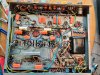
Update: I don't quite have all the parts for the IBAM yet, but I tried out #2 from the previous post. I made a separate RC filter directly off the bridge rectifier using a 3 ohm 5W resistor and a 68uF 100V capacitor. Using that leading into the IBBA, I was able to get enough negative voltage to properly bias the 7591's. I got all of them running at 32 mA. At 430V plate voltage, that's about 430*0.032=13.76W which is about 72% of the max plate dissipation. Not bad! Still tinkering around with different combinations of the RC filter and the CL-80's I put in, but so far it's looking good!
There's still an obnoxious buzz coming out of the speakers. Not sure what to do about that...
There's still an obnoxious buzz coming out of the speakers. Not sure what to do about that...
carlman14
Member
Glad it worked out for you! Now how does it sound???
Well... I still have some work to do. There's two current problems:
- The left channel has gotten even weaker, to the point there's almost no sound coming out of the channel.
- There's still that awful buzz coming from the speakers.

kvflyer
Super Member
Do you have a marked up schematic of how you implemented the IBAM? What part of the original circuit did you replace, or where did you tie it in?
+1 on the tube sockets, especially the 7199’s.
"Unfortunately" a lot of the 7199 tubes out there, which have some time on them, can have grid emission. They were run very close to the edge with voltages near maximums. I have a few that test good. But they exhibit grid emission. Being an LK-72, it is a simple matter to change the wiring for a 6GH8/6U8. Scott did that in later amplifiers.
carlman14
Member
Do you have a marked up schematic of how you implemented the IBAM? What part of the original circuit did you replace, or where did you tie it in?
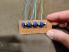
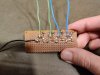
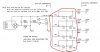
Sure, I can share what I did! I used the IBAM schematic that's floating around the forums that was originally used for the Fisher amps (attached). I circled the part that's relevant. All the rest is specific to the Fisher amp it was designed for.
Basically, after it's implemented, you'll want to remove the negative bias supply wire going from the 75/75/75/75 cap to the 4 output tubes. This wire goes to two tie-points that sit in front of the 7591 pairs. Those points have 330 ohm grid resistors tied together. After the negative bias wire is removed from those points, connect it to the "(-) bias supply" on the IBAM schematic.
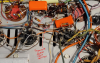
Make sure to separate the 330k resistors at those tie points (attached a pre-IBAM pic to show where this point is).
Now just run wires from the 4 output spots on the IBAM schematic to those 4 330k resistors that have been separated, and that's it! But also make sure the IBAM is grounded too.
Last edited:
carlman14
Member
The tube heater’s for V1,2,3,&4 still need to be fed from the bias though, so you can’t just remove them from the circuit. Maybe I’m misunderstanding how you dealt with that.
Ohhh that's my bad. I mistakenly thought V1-V4 to be the 7591s. I'll remove the picture so there's no confusion. For clarity, the only wire that needs removing is the one that goes from that -45V bias to the 7591 grid tie points.