• The move to the new server is done. There are some software and database maintenance updates in process. This has us passing the hat around to help out. We appreciate any donations. Seriously, even a dollar helps. The payment page may be found here - https://www.audiokarma.org/support.html

HK CD 401 idler tires confusion!

Well I thought I'd update this, unfortunately, looks like a bad ending, but something unrelated to the transport.

I ended up getting a couple of the slightly oversized tires for the white pulley. I then carefully spun them on my drill with a dowel shaft against 150 grit sandpaper which shaved them down pretty cleanly.

I could not take enough off the thinner white pulley tire, so I also shaved a fraction off the adjacent black pulley tire (the sankyo transport small tire).

Went little by little, first try too tight, secondary motor belt for the clutch would slip. Took several times to finally get the right amount off to where the transport works perfectly!

Now the bad ending. After putting it back together for the umpteenth time and hooked it up, my left channel is now gone. Hiss comes through, and a tiny sound bleeds through like it's on mute. Both channels were perfect before.

I'm really bummed, after all this to get the transport working. I guess I must have messed something up during the many attempts on the transport, but I was very careful, and never had to remove the transport or much of anything else to work on the clutch pulleys. The only wiring I removed was when removing the faceplate, there are two multi pin connectors that snap out out and one ground. Double checked it's all back as before.

I am giving up on this thing :(. Unless of course someone might have a clue what went awry with the left channel. I'm not sure where to look.
 
Why would you give up? It's not like you tried everything you could think of to fix this particular problem.. Sure I understand the frustration. Just put it away for a few days or so. You did a great job on the transport, and that is working now right? You are not stuck, it's just a bit further still.

It's probably just some contact or solder joint that got a little lose from the wiggling. I would first try carefully fiddling around a bit while it's playing to see If anything pops up. If not, you are sure to find the culprit by signal tracing.
 
Appreciate your encouragement. Yes transport is now working great. Today I will see if it records on both channels, I suspect it will and I can at least use it to make some nice sounding tapes.

I visually inspected and poked a few things, nothing obvious. Even the cheap light blue 10 uf caps all look good, and I doubt it's a cap considering the channel just went out abruptly.

WRT signal tracing, I'm not sure where to start, and have a basic meter with minimal experience diagnosing electronics. I can't find a schematic in the service manual I downloaded? On page 15 there's a brief description of the playback circuit, but again no diagram or anything showing the voltages I'd want to test.

Thanks again
 
Last edited:
I suspect you broke one of the head wires. Follow the wires from the record/playback head to the pcb. Put the deck in play and touch a small screwdriver to the terminals where the head wires attach. You should get him on both channels.
 
I have not checked the wiring from the head yet because it's hooked up for a recording test. Results:

When setting the bias trim, nothing shows on the left vu meter. When adjusting the recording calibration, same result.

However, when I actually record from a source, both vu meters are working and upon playback on another deck, both channels recorded.
 
This proves the problem is in the output circuit, not the head wires. I'll see if I can find a schematic.
 
That makes perfect sense if the left playback channel is cut somewhere.

WRT signal tracing, I'm not sure where to start, and have a basic meter with minimal experience diagnosing electronics. I can't find a schematic in the service manual I downloaded? On page 15 there's a brief description of the playback circuit, but again no diagram or anything showing the voltages I'd want to test.

Thanks again
NP!
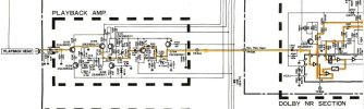
About the schematic: It is available at hifiengine.com If you haven't yet just subscribe, it's totally free. And lucky you, there is an excellent schematic available there, with a neat coloured line for the audio signal path! Here's a detail to give you an idea.


ampy.jpg

It looks as if there are many separate PCB's in this machine, so you could do a fair bit of diagnosing here without using any measuring instrument at all. This is exciting new stuff man!:D What you could do is simply cross the wires between left and right, between two sections. Like here between the playback amp and the dolby amp (or section). Do you now have sound on the left, but not on the right? Then the problem must be somewhere before the dolby amp. Still no sound on the left, but only on the right? In that case the problem must be after the playback amp. You go systematically along the signal path, and that is how you determine from whereon switching the input left and right makes a difference. We'll take it from there.
 
Thanks guys! That schematic is great.

When you say cross the wires at various points, does that mean unsoldering and resoldering? Just not sure how I'd easily switch the wires / channels.

I did also notice that when recording, pressing the tape monitor resulted in the left channel drop which I guess I expected. But what surprised me was that the tape monitor had no effect on the working playback of the right channel. That is, increasing or decreasing the line level had no effect on the output of the right channel when recording with the tape monitor on.
 
Thanks guys! That schematic is great.

When you say cross the wires at various points, does that mean unsoldering and resoldering? Just not sure how I'd easily switch the wires / channels.

I did also notice that when recording, pressing the tape monitor resulted in the left channel drop which I guess I expected. But what surprised me was that the tape monitor had no effect on the working playback of the right channel. That is, increasing or decreasing the line level had no effect on the output of the right channel when recording with the tape monitor on.
Make sure you have the deck connected properly. Tape Out on the reciever to Tape In on the deck and Tape In on the receiver to Tape Out on the deck. The sound level not changing is a symptom of reversed cables.
 
Yes, check that ^^^^ first

When you say cross the wires at various points, does that mean unsoldering and resoldering? Just not sure how I'd easily switch the wires / channels.
Yes you might have to unsolder wires, or switch the pins in a connector, or whatever gives. Bare in mind that a wire connection is just that. So you can either temporarily or permanently replace it with any piece of wire that is more convenient, as long as it connects on both ends.
 
The meter circuit is connected to the output jacks. Since you have no output on the left channel both on Tape and Source, that vindicates all the circuitry before the output, except for the output jack and the output level calibration trimpot, VR301, which is probably dirty. Mark the position of the pot with a sharpie on the board, then turn the pot back and forth a few times and see if you get output. If so, clean it with Deoxit and return it to it's original position.
1689164754331.png
 
I have not checked the wiring from the head yet because it's hooked up for a recording test. Results:

When setting the bias trim, nothing shows on the left vu meter. When adjusting the recording calibration, same result.

However, when I actually record from a source, both vu meters are working and upon playback on another deck, both channels recorded.
If you have multimeter you can try the following

On your deck, set VU at 0dB, Bias center, Dolby OFF, MPX OFF
Record 400Hz using your smart phone signal gen app.
Then play back the recording and attach multimeter in AC mode to TP501 and TP502, both TP should be about the same and at about ~400-700mV ( 0.4-0.7V )
If not, there is an issue with playback head wires or something along the audio path up to dolby amp chip
 
Wow thank you so much, that really helps me zero in. And yes, it's hooked up correctly. I made two tapes today and this is quite a machine. Played back on my HK CD 191 they sound super.

I plan to make a few more tapes in the coming days and then I'll unhook and try these suggestions. The VR 301 suggestion sounds spot on.

Thank you AK friends!
 
The meter circuit is connected to the output jacks. Since you have no output on the left channel both on Tape and Source, that vindicates all the circuitry before the output, except for the output jack and the output level calibration trimpot, VR301, which is probably dirty. Mark the position of the pot with a sharpie on the board, then turn the pot back and forth a few times and see if you get output. If so, clean it with Deoxit and return it to it's original position.
View attachment 2931460

Ok I checked this today, and after a half hour of not being able to locate a VR301 trim pot on any of the boards, I checked the schematic and the schematic diagram shows what you are showing, but the wiring diagram on the next page shows that VR301 and VR302 are actually the output level pot adjusted via the single knob. Interesting that it shows 301 and 302 housed in a single pot, I guess two contacts in a single pot off one shaft.

At any rate, I gave the output level pot a good Deoxit blast and unfortunately the left channel is still not working.
 
Ok I checked this today, and after a half hour of not being able to locate a VR301 trim pot on any of the boards, I checked the schematic and the schematic diagram shows what you are showing, but the wiring diagram on the next page shows that VR301 and VR302 are actually the output level pot adjusted via the single knob. Interesting that it shows 301 and 302 housed in a single pot, I guess two contacts in a single pot off one shaft.

At any rate, I gave the output level pot a good Deoxit blast and unfortunately the left channel is still not working.
Next clean the tape / source switch.
 
Next clean the tape / source switch.
I did! Sorry I should have mentioned before putting this into service, I did a thorough cleaning and Deoxit bath on all switches and pots. Everything worked perfectly until the clutch tire failed, then after fixing that, the left output channel went out.

I did another cleaning of the tape monitor switch when I hit the output level pot again. Still no luck.

I did not test the other voltages from the tape head as also suggested based on the assessment that path was good based on my other findings. Sounds like I should, if you can focus me on a specific area that would be great.
 
I would not bother with checking voltages. This type of problem is best fixed by tracing a signal though the circuits and seeing where it is lost. A scope is best for this but you don't have one so we can try to use your meter but we need a reliable constant signal source. Lets try using the calibration tone that is built into the deck.
1. Turn the cal tone on.
2 Put the tape / source switch in Source.
3. Set your DMM to AC Volts, 200mV range.
4. Connect the - lead of the meter to ground or the chassis.
5. Touch the + lead to either end of C573 (L Ch) and C574 (R Ch)
What are the readings?
 
Well I feel like a complete dope, but for the life of me, I cannot find C573 or C574. I find everything around it, such as C572 and C575, etc.. I could not find it in either the wiring diagram that shows all pcb components, or by looking at the board itself.

According to the service manual, it is a 1uf, which I think is one of those little red flat capacitors. I also checked the other smaller boards except one that is buried, I think that is for bias.

Can you clue me in where I find these!?
 
Back
Top Bottom