

You are using an out of date browser. It may not display this or other websites correctly.
You should upgrade or use an alternative browser.
You should upgrade or use an alternative browser.
HK CD 401 idler tires confusion!
- Thread starter smead
- Start date

Ok, I hit C307 and got a little static pop when connected, but silent thereafter, no 12htz tone through the speakers. You guys have been so helpful and patient with me, but if you can error on the side of being overly explicit with the next steps that will surely help this old guy newbie. I'm learning a lot throughout this process and am so appreciative of the help I've received, hopefully it'll also result in getting this deck back to life!
Thank you!
Thank you!

Sorry, I don't mean to intrude @dr*audio. Keep up the good work.Ok guys I did the baseline, one end on R479, the other on the output jack (bottom lead on J5 on PCB9). I do hear the high pitched 12khz signal through the left channel. A modicum of progress!
I thought you were looking for the 400Hz test tone? Not 12kHz? Not sure what you are hearing.
A 400Hz tone should sound like this... At 12kHz, you 'almost' can't hear it.
Last edited:

dr*audio
Fish fingers and custard!
I think it only puts out 400 Hz when you hold the Cal Tone switch in. There is also a Bias Tone switch which should put out 12KHz. If the Bias switch is pushed in, and it's the kind that stays in, push it so it is out, and push the Cal Tone switch, if that switch stays in. If both are momentary contact, just continue to use the 12KHz tone. As long as you can hear it, it doesn't matter.I think this HK deck puts out a 400hz tone in one channel, 12khz in the other. When I connected to the left output jack, I hear a very high frequency tone that must be the 12khz?
So now we need to check if the problem is on the output side of C307. There is a muting transistor that may be shorted on turned on.
1. Measure the voltages on Q757; E, C, B and record them here.
2. Turn the deck off, put your meter on OHMs and measure the resistance between Q757 collector and ground.
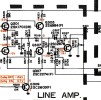
Just to be clear, the bias and tone cal switches do not stay in press pressed - must press and hold. When I get the 12 khz tone through the left output channel when jumping it to r479, I was assuming the tone came from there.
For the Q757 readings, I removed the jumper from r479 used to test c307. I then powered on the deck, set my DMM to AC Volts, 200mV range. I connected the - lead of the meter to chassis.
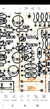
Not being sure which pins are ECB, I measured each at zero, wasn't sure if I needed to press the tone cal button, I did this and got 0, 0, 1.8 starting from top to bottom in the photo.
Forr resistance, I got 0, 2.1, 0 ohms readings, again with DMM - lead grounded on chassis, unit powered off.
Did I do this right? Or was I supposed to leave c307 jumped to R479?
For the Q757 readings, I removed the jumper from r479 used to test c307. I then powered on the deck, set my DMM to AC Volts, 200mV range. I connected the - lead of the meter to chassis.
Not being sure which pins are ECB, I measured each at zero, wasn't sure if I needed to press the tone cal button, I did this and got 0, 0, 1.8 starting from top to bottom in the photo.
Forr resistance, I got 0, 2.1, 0 ohms readings, again with DMM - lead grounded on chassis, unit powered off.
Did I do this right? Or was I supposed to leave c307 jumped to R479?
Attachments
dr*audio
Fish fingers and custard!
For the voltage readings I should have told you to set your meter on DC Volts, but it doesn't matter, it looks like Q757 is shorted.Just to be clear, the bias and tone cal switches do not stay in press pressed - must press and hold. When I get the 12 khz tone through the left output channel when jumping it to r479, I was assuming the tone came from there.
For the Q757 readings, I removed the jumper from r479 used to test c307. I then powered on the deck, set my DMM to AC Volts, 200mV range. I connected the - lead of the meter to chassis.
Not being sure which pins are ECB, I measured each at zero, wasn't sure if I needed to press the tone cal button, I did this and got 0, 0, 1.8 starting from top to bottom in the photo.
Forr resistance, I got 0, 2.1, 0 ohms readings, again with DMM - lead grounded on chassis, unit powered off.
Did I do this right? Or was I supposed to leave c307 jumped to R479?
You will need a soldering iron with a small tip (smaller than 1/8") and solder removal braid. Do you have these?
dr*audio
Fish fingers and custard!
You did not need to press the Tone Cal.Yes I do, I have replaced a couple of transistors on some of my receivers. Are you sure I did everything right taking those measurements? Did I need to press the tone cal? R479 jumper supposed to be removed?
The transistor reads a dead short across it. Take a picture of it so you know how it was installed, then very gently wick the solder off the pads for the transistor and remove it. Don't throw it out! Then see if you have output on both channels when you set the tape switch to source and apply a signal to the input jacks from a CD player or something.
Thank you so much for getting me this far. Unfortunately, murphy's law seems to be conspiring against me with this deck. Both sides of the main pcb board are easily accessible. But Q757 is on a smaller board facing the bottom of the chassis. The solder side is not easily accessible, has other boards stacked on top of. It has to come out, and I'm not seeing an obvious means of doing so. Can't even see how it is secured.
May I ask what reading I took that tells you Q757 is shorted? I'd be curious to take the readings on the corresponding right channel transistor to compare them.
If Q757 is definitely the culprit, I'll need to decide whether or not to risk further damage doing a complex extraction. As it stands now, the deck makes great tapes, and as much as I'd like playback, I don't want to lose what I have.
May I ask what reading I took that tells you Q757 is shorted? I'd be curious to take the readings on the corresponding right channel transistor to compare them.
If Q757 is definitely the culprit, I'll need to decide whether or not to risk further damage doing a complex extraction. As it stands now, the deck makes great tapes, and as much as I'd like playback, I don't want to lose what I have.
dr*audio
Fish fingers and custard!
I asked you to measure the resistance from Q757 collector to ground. (Actually I meant the emitter but you measured all 3 pins so we got the information we needed.) It should have been some larger resistance, at least 1K Ohm on the emitter but it was 0 or 2, I forget which. Either way that is too low and unless you probed the wrong lead or shorted 2 leads together, it indicates the part is bad. It's a muting transistor and it's supposed to mute the output when the deck is first turned on or off so that there isn't a pop in the output. The deck will work without it, which is why I asked you to remove it. You can check Q758 and compare. By the way, when you are looking at the transistor from the flat side, the leads are ECB. So just measure from the left hand lead, looking at the flat side, to ground. With the power off.Thank you so much for getting me this far. Unfortunately, murphy's law seems to be conspiring against me with this deck. Both sides of the main pcb board are easily accessible. But Q757 is on a smaller board facing the bottom of the chassis. The solder side is not easily accessible, has other boards stacked on top of. It has to come out, and I'm not seeing an obvious means of doing so. Can't even see how it is secured.
May I ask what reading I took that tells you Q757 is shorted? I'd be curious to take the readings on the corresponding right channel transistor to compare them.
If Q757 is definitely the culprit, I'll need to decide whether or not to risk further damage doing a complex extraction. As it stands now, the deck makes great tapes, and as much as I'd like playback, I don't want to lose what I have.
Ok thanks I'm glad I checked Q758. I get the exact same readings there, and we know the right output channel is good, so something is amiss here. I'm putting the black lead to the chassis, red lead on the pins, DMM set to 200 ohms. I took a reading of a 4 ohm a car speaker to verify the DMM is working and got a reading of 4.1.
@smead, are you positive that the DMM is not displaying "OL" vs "0"? You may want to change the scale to something like 2K or 20K ohms and try again.DMM set to 200 ohms.
dr*audio
Fish fingers and custard!
Ok, now that I see where you were measuring, Q757 looks ok.Yes it is not reading 0L. I set it to 20K and Q757 reads 0, .01, 2.5 measuring from top to bottom per the image I posted earlier.
1. With your meter set to 200 Ohm range and the unit OFF, measure from each of the 2 outer pins of the output level control to ground on both sections of the control. One of the pins on each section will be 0 Ohms. That is the ground connection and I need you to make note of which pins go to ground.
2. Reconnect your jumper probe to the tone generator circuit.
3. Connect the outputs of the deck to an amp so you can hear it.
4. Put the tape / Source switch in Source.
5. Touch the jumper to each of the center pins on each section of the output control. Do you hear the tone?
6. Now touch the jumper to each of the outer pins that are NOT the ground connection on each section of the output control. Do you hear the tone when you touch each of the pins?
7. Turn the unit off and disconnect the jumper.
8. Turn the unit back on.
9. Set your meter to the 20V range, DC volts.
10 Clip the black meter lead to the chassis.
11. Wrap a piece of tape around the tip of the red meter lead so that only the very tip is exposed (to prevent shorting things out) Measure the voltage on Q757 top lead in your picture. That's the base.
12. Measure the voltage on Q758 top lead.
Last edited:
Thank you for hanging with me. I have to go out of town for a couple of days for some family caregiving duties, when I get back I'll take these measurements and report back. Just to be clear, step 2) "Reconnect your jumper probe to the tone generator circuit" means one lead on R479 right? Thanks!
dr*audio
Fish fingers and custard!
Correct.Thank you for hanging with me. I have to go out of town for a couple of days for some family caregiving duties, when I get back I'll take these measurements and report back. Just to be clear, step 2) "Reconnect your jumper probe to the tone generator circuit" means one lead on R479 right? Thanks!
Ok I had some time this morning to take these measurements.
DMM set to 200 ohms, measured outer pins on VR301 and VR302. Both right leads measure 0, both left leads measure 2.5. Those are not the ground side.
Powered unit on and connected tone cal jumper.
"Touch the jumper to each of the center pins on each section of the output control. Do you hear the tone?"
On VR 301 (left channel), no. On VR 302 (right channel), yes.
"Now touch the jumper to each of the outer pins that are NOT the ground connection on each section of the output control. Do you hear the tone when you touch each of the pins?"
Yes I do on both VR 301 and 302.
"7. Turn the unit off and disconnect the jumper.
8. Turn the unit back on.
9. Set your meter to the 20V range, DC volts.
10 Clip the black meter lead to the chassis.
11. Wrap a piece of tape around the tip of the red meter lead so that only the very tip is exposed (to prevent shorting things out) Measure the voltage on Q757 top lead in your picture. That's the base.
12. Measure the voltage on Q758 top lead."
.01 on top lead Q757. Q758 is soldered in 180 degrees backwards compared to Q757, so base must be the bottom lead. It also measured .01.
DMM set to 200 ohms, measured outer pins on VR301 and VR302. Both right leads measure 0, both left leads measure 2.5. Those are not the ground side.
Powered unit on and connected tone cal jumper.
"Touch the jumper to each of the center pins on each section of the output control. Do you hear the tone?"
On VR 301 (left channel), no. On VR 302 (right channel), yes.
"Now touch the jumper to each of the outer pins that are NOT the ground connection on each section of the output control. Do you hear the tone when you touch each of the pins?"
Yes I do on both VR 301 and 302.
"7. Turn the unit off and disconnect the jumper.
8. Turn the unit back on.
9. Set your meter to the 20V range, DC volts.
10 Clip the black meter lead to the chassis.
11. Wrap a piece of tape around the tip of the red meter lead so that only the very tip is exposed (to prevent shorting things out) Measure the voltage on Q757 top lead in your picture. That's the base.
12. Measure the voltage on Q758 top lead."
.01 on top lead Q757. Q758 is soldered in 180 degrees backwards compared to Q757, so base must be the bottom lead. It also measured .01.