• The move to the new server is done. There are some software and database maintenance updates in process. This has us passing the hat around to help out. We appreciate any donations. Seriously, even a dollar helps. The payment page may be found here - https://www.audiokarma.org/support.html

HK CD 401 idler tires confusion!

Ok I had some time this morning to take these measurements.

DMM set to 200 ohms, measured outer pins on VR301 and VR302. Both right leads measure 0, both left leads measure 2.5. Those are not the ground side.

Powered unit on and connected tone cal jumper.

"Touch the jumper to each of the center pins on each section of the output control. Do you hear the tone?"

On VR 301 (left channel), no. On VR 302 (right channel), yes.

"Now touch the jumper to each of the outer pins that are NOT the ground connection on each section of the output control. Do you hear the tone when you touch each of the pins?"

Yes I do on both VR 301 and 302.

"7. Turn the unit off and disconnect the jumper.
8. Turn the unit back on.
9. Set your meter to the 20V range, DC volts.
10 Clip the black meter lead to the chassis.
11. Wrap a piece of tape around the tip of the red meter lead so that only the very tip is exposed (to prevent shorting things out) Measure the voltage on Q757 top lead in your picture. That's the base.
12. Measure the voltage on Q758 top lead."

.01 on top lead Q757. Q758 is soldered in 180 degrees backwards compared to Q757, so base must be the bottom lead. It also measured .01.
According to the schematic, the center taps of the pots are the output, so it doesn't make any sense that you should get output from the outer pins and not from one center pin, unless the pots are not wired per the schematic.
No matter, the problem seems to be a bad output control. You don't really need it so you can defeat it:
Solder a wire from the non - ground outer pin to the center pin for each section. That will make it always all the way up. You do need to leave the control turned up all the way, though.
 
Is it possible that I am not getting a signal into VR 301? Or is that verified by the fact that I do get a signal through the left non-ground outer pin?

I hooked up a temp jumper between the middle and non-ground pins on VR 301 to verify I'll get output from the left channel. But I do not?

Would I also need to jump the same pins on VR 302 (working right channel) to effect the jumping of VR 301? I hope not, because while the pins on VR 301 are accessible to solder, not the case with 302 unless I pull the board which looks like a PITA.

I'm hopeful we're getting close, thank you!
 
Is it possible that I am not getting a signal into VR 301? Or is that verified by the fact that I do get a signal through the left non-ground outer pin?

I hooked up a temp jumper between the middle and non-ground pins on VR 301 to verify I'll get output from the left channel. But I do not?

Would I also need to jump the same pins on VR 302 (working right channel) to effect the jumping of VR 301? I hope not, because while the pins on VR 301 are accessible to solder, not the case with 302 unless I pull the board which looks like a PITA.

I'm hopeful we're getting close, thank you!
We are getting close. It looks like VR301 is not the problem, but your results above make no sense. You had sound when you touched the jumper from the cal tone circuit to the outer pin of R301 but not when you touched it to the center pin, so shorting the 2 together should have given you output if you had the control turned all the way up.
You heard the test tone when you jumpered it to R331, so we know everything from there to the output is ok, and you heard the test tone when you jumpered it to R301 outer pin, so we know that everything from there to the output jack is ok. Is it possible you weren't making contact when you jumpered the 2 pins on R301, or shorted the center pin to the ground pin?
 
On VR 301 and 302, there are 3 flat lead terminals on the side of each pot. But they go into the board via 6 small pins on each pot. I've been assuming the two pins on each lead are the same, and pins 3 and 4 are the center lead. Could I be making a wrong assumption?

When I did the test jumper, I jumped to the leads on the side of VR 301.

EDIT: My assumption about the pins (2 one in the same per lead) was based on you asking me to test the CENTER lead. With 6 pins per pot, I assumed pins 3 and 4 were the center.

EDIT 2:. Not sure if it matters, but I'm jumping to R479. I was never able to find R331.
 
Last edited:
1689949904235.png
Look at this, there are 2 output level controls VR101 and VR102 in the upper right hand corner that are not on the schematic! Try turning them back and forth a few times and see if you get output!
 
Those are adjusted with a tiny screwdriver through a hole in the back of the chassis. Because I cannot see the top of the trim pot, I cannot mark it so once turned would be difficult to put back to where it was.

There are two pins on each, would it work and be safe to just jump those pins to test for output?
 
Those are adjusted with a tiny screwdriver through a hole in the back of the chassis. Because I cannot see the top of the trim pot, I cannot mark it so once turned would be difficult to put back to where it was.

There are two pins on each, would it work and be safe to just jump those pins to test for output?
Just leave them all the way clockwise, looking at the shaft end.
 
If these are the holes you talk about they are to adjust setting Dolby levels... DON'T touch these unless you have a Dolby calibration tape.
If there are other controls, I can't see them in this photo?
1689983270548.png
Look at this, there are 2 output level controls VR101 and VR102 in the upper right hand corner that are not on the schematic!
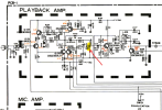
VR101 & VR102 are on the schematic and they are NOT output level controls. They are located in the Playback Amp before the Dolby circuit. Looks like they are used to set the Dolby reference level into the Dolby decoder.
1689984406736.png
 
Last edited:
If these are the holes you talk about they are to adjust setting Dolby levels... DON'T touch these unless you have a Dolby calibration tape.
If there are other controls, I can't see them in this photo?
View attachment 2939198

VR101 & VR102 are on the schematic and they are NOT output level controls. They are located in the Playback Amp before the Dolby circuit. Looks like they are used to set the Dolby reference level into the Dolby decoder.
View attachment 2939216
Ah, ok, I didn't see these on the schematic. They are upstream of the problem area and will not cure the problem. Leave them alone.
 
Arg, too late. I thought it was odd that we were messing with VR 101 when it sounded like you had isolated the left channel drop to VR 301 based on my prior measurements.

Earlier this morning I moved VR 102 first to verify the right channel volume changed. It did. I then moved VR 101 and it had no effect on the silent left channel. I tried to put them back where they were by feel. Bummer.
 
On VR 301 and 302, there are 3 flat lead terminals on the side of each pot. But they go into the board via 6 small pins on each pot. I've been assuming the two pins on each lead are the same, and pins 3 and 4 are the center lead. Could I be making a wrong assumption?

When I did the test jumper, I jumped to the leads on the side of VR 301.

EDIT: My assumption about the pins (2 one in the same per lead) was based on you asking me to test the CENTER lead. With 6 pins per pot, I assumed pins 3 and 4 were the center.

EDIT 2:. Not sure if it matters, but I'm jumping to R479. I was never able to find R331.
Can you take a photo (hopefully using a real camera, not a cell phone) in focus, of the board side of VR301 and VR302, also showing the traces so I can follow them and see where they go? The service manual I found doesn't have a PCB layout.
 
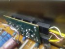
Here's the top side of the board showing the back of VR301. You can see the three round flat leads that I was taking my measurements from, and below it appears that each lead has two pins into the board, 6 total.

I cannot see the solder / trace side of the board, it is buried below several smaller boards.
 

Attachments

  • IMG_20230722_100022.jpg
    IMG_20230722_100022.jpg
    80 KB · Views: 8
It all becomes clear now! Thanks for the photo, and thanks for clue-ing me into where the pcb layout is. I thought there was only a schematic in that file.
You were probing the wrong places on R301 and R302! Those flat tabs hold the board on to the case of the control and they connect to ground!
I also found R331, see below.
Reconnect your jumper to R479.
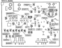
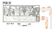
Locate the board below.
Locate P181.
Connect the output to your amp so you can hear it.
Turn the power on.
The deck in stop mode,
Tape / Source switch to Source.
Touch the other end of the tone jumper to P181 where the red wire connects, then where the white wire connects.
Do you hear the tone both places?
If so, follow the wires to where they attach on the other end and repeat at the other end.
1690065569592.png
 
PCB-9 is located on the back panel here:
1690074006361.png

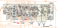
The other side of the wire on P181 connects to here:
1690074276328.png

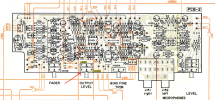
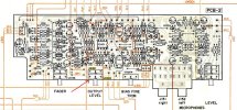
on PCB2:
1690074415417.png
 
Last edited:
Thanks guys, I'm out of town again, will be back tomorrow and will follow the above steps and report back.
 
"Reconnect your jumper to R479.
Locate the board below.
Locate P181.
Connect the output to your amp so you can hear it.
Turn the power on.
The deck in stop mode,
Tape / Source switch to Source.
Touch the other end of the tone jumper to P181 where the red wire connects, then where the white wire connects."

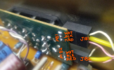
OK I'm sure I found it, but as you can see in the photo, the outside wires are both white, inside yellow.

"Do you hear the tone both places?"

Tried both outside leads, I hear nothing in either speaker.

"If so, follow the wires to where they attach on the other end and repeat at the other end."

Following the tip from dankik, I see the other ends next to VR301/302, connected there and no sound from either side.
 

Attachments

  • IMG_20230726_133944.jpg
    IMG_20230726_133944.jpg
    76.2 KB · Views: 2
OK I'm sure I found it, but as you can see in the photo, the outside wires are both white, inside yellow.

This board diagram looks like the component side of the board. Your photo is of the trace side of the board. It's flipped from your photo, verify it. Both wire are not white, one is white the other is pink (or sort of) from you photo.
1690409283459.png
1690409627152.png
 
Back
Top Bottom