• The move to the new server is done. There are some software and database maintenance updates in process. This has us passing the hat around to help out. We appreciate any donations. Seriously, even a dollar helps. The payment page may be found here - https://www.audiokarma.org/support.html

Klipsch Jubilee Crossover Network

Status
Not open for further replies.
Krytar,

Excellent on the EQ! I would like to see the design too. I promise to keep it confidential.

BTW: I realized that with the EQ I lashed up, an autotransformer turned backward would nicely match the 4.8 Ohm network output to a higher Zo and level. The actual setting would have to be worked out though. I think you could maybe get 4 - 6 db boost without much trouble.

Al K.
 
The second plot looks a good deal better than the first.

I have received NOTHING from you lately. I did not even receive a confirmation that you received my new Jubilee network design when I email it to you.

Al, I emailed you the plot some time ago (the same one I just posted). I sent it so you could work your EQ solution for the big horn. After I sent it, you emailed me the Jubilee design you did for JC, which I knew would have been for the K-510 horn, which didn't do me any good since like Richard, I have the K-402. In the email or on the phone, I can't remember which, you stated that after equalization the system was approximately 90dB or a bit more. No one should have to state what is obvious -- it's incompatible with an LF section that's 15dB higher in sensitivity.

That plot you posted, I have seen it before and I am not convinced it applies to Richards horn.

That's the correct plot.

If the Klipsch high end is not hot enough for passive equalization then it must be equalized by an active unit ahead of the amp.

I explained how that works. With the passive, the elevated or lower end of the driver's response is brought down, with the active, the falling response is boosted.

I would use a horn with a flat on-axis response for a home system.

IOW's, a horn that collapses the vertical response and lifts the output as frequency increases (beams). Sure, you can do that, but then you lose the benefit of what a constant directivity horn provides. The soundstage is huge.

If, on the other hand, that crappy passive network DelGado did actually yields a flat response then passive is possible.

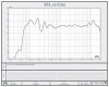
It's +/-5dB through the top section. Plot attached. Delgado's comments regarding the LF response in the plot are as follows:

"...in full space, 3m out, the bass is not accurate from about 150 hz down because of the size of our anechoic chamber. Moving in to 1m full space, the bass begins to look like a ground plane measurement in our chamber. 1/8 space curves suffer from distance problems as well. At 3m, the measurement is still at the mercy of the chamber size although, not as bad as full space. Moving in to 1m helps out a lot, and you can start to rely on the info you are seeing."

 

Attachments

  • JUBNET%20copy.jpg
    JUBNET%20copy.jpg
    128.5 KB · Views: 40
Krytar,

I did a little fiddling in the computer by combining the output of the high channel of my Jube network through a transformer with a 2:1 turns ratio transformer into my kluge eq. The results were not very promising. The best I could get was about a 5 dB overall change in level from 600 to 20 KHz and maintain a descent return loss. My measurements on the K-69 driver showed it went from 8 to about 13 Ohms, so I assumed a termination of 10 Ohms. I hope your EQ is better!

AL K.
 
Krytar,

Take a look at the attached PCFILT schematic. It's a constant impedance amplitude equalizer topology that I have programed in. It's on of my standard networks. Is it the one you are using? Don't pay any attention to the part values. It's just any old equalizer that happens to be the right Zo. It's a NON-design!

AL K.
 

Attachments

  • Eq_xx.gif
    Eq_xx.gif
    11 KB · Views: 27
New Equalizer

Dean,

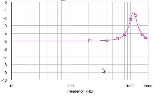
Here is another equalizer for you latest curve. There is no thing I can do to help the valley at 230Hz.

Data included the transmission response & return loss. Here is the plot:

Equalizer_Dean3A.gif
 
Krytar, it's pretty much impossible to get flat response from a folded horn, people use them for the low distortion and realistic dynamics. At any rate, once placed in a room, the LF response may or may not bear much resemblance to that in the second chart, which by the way is the in-network FR response. Carefully compare the first chart I posted to the second, you will see that from 6kHz onwards they are identical (you don't EQ the whole response). Like I said earlier, I think the peak at the end is left in place by design.

Experimenting with passives is expensive, especially when you build like I do. Even with inexpensive caps, a stack of litz coils can set you back quite a bit. Multiply that by the variations and the checking account takes a pretty good hit. I wish I had the play money (and the time) I had a few years ago, I certainly wouldn't mind building all of the options, and active filtering looks interesting too. I provided the first plot so you guys could work from something trustworthy, primarily for Richard's benefit, since he still has interest in a pair of ESN passives. If it works out and they sound good, I'll give it a whirl down the road -- I just can't afford to sink money into potential possibilities, it has to be a for sure thing.

Al, if you can get 5dB with an autoformer, I think that might be enough. If you look at the second plot I posted, most of the response of the top section is hovering at 100dB, and much of what's in your plot would be right in there with the 5dB of boost. Do your models account for the 45 degree phase shift at the corner frequency when an autoformer is used? Just curious. I strongly suspect Klipsch and Delgado tried where you are going, I'm pretty sure they tried the autoformer in reverse with the prototype.
 
Dean,

I'm not sure what the autoformer will give me. I am in the process of programing the ability to equalized tabulated performance data like the curve you posted, into PCFILT. The K-69 looks like about 10 Ohms. the ratio of 10 : 4.8 ohms will only boost voltage about 1.4 times. That's not a lot. I'll have a better idea what the results will be when I get further into the project. A 16 Ohm driver would probably do a lot better.

AL k.
 
Hi Dean,

Please clarify:

1) How was the curve measured? (with active Xover in the system (?))

2) No need of equalization for the low end (50-500Hz), only hi freq (1Khz-18 KHz) needs to be equalized?

If you need only to equalize the high end (like my second data plot) then a simple equalizer would do the job. Tolerance of components are taken into account when I computed the network.
 
What a wasting effort for Al to convince those Klipsch engineers to improve their design.

To my disbelieve that how Klipsch have been using very bad designs in their systems. I looked at their circuit designs, and just wonder how could they come up with something like that.

krytar,

I don't think you've seen any of the new designs, Klipsch doesn't let them out. :D

It looks like you also don't understand manufacturing and marketing for consumers. If Klipsch bought a design from the outside and it got out, their image would be damaged. Klipsch does not want a lawsuit for copyright infringement, either.

I have some knowledge of some of the crossovers used in the 60s through the 80s and they are not bad designs. Most are engineered designs, done well, with enough quality and performance to meet the requirements of the day (the real definition of engineering). I have also had the rare previledge to see the schematic of one of the newest crossovers for the old line of speakers. I find it overly complex, like many of Al's designs. It also has some EQ built into it. I'm not so sure the speaker needs EQ, but the results sound quite good.

I would like to know more about the Jubilee and it's crossovers. Since it has not been produced for the public, we'll have to wait for a bit longer. I know the treble horn is a CD horn. CD horns have several nice attributes, but a passive crossover for them is challenging to design. I've done one and I'm not sure what I think of the result.
 
1) How was the curve measured? (with active Xover in the system (?))

The first plot I posted earlier is the out-of-network response (raw), the second plot is in-network. Both were done in the Klipsch anechoic chamber with 2.83v applied.

2) No need of equalization for the low end (50-500Hz)...?

For the most part. There is one trap to pull down the big peak at 1500Hz.
 

Attachments

  • JLF.jpg
    JLF.jpg
    73.3 KB · Views: 27
I would like to know more about the Jubilee and it's crossovers. Since it has not been produced for the public, we'll have to wait for a bit longer. I know the treble horn is a CD horn.

There are close to a dozen Jubilee owners now. If you're interested, you can PM me for details. The horns are CD, but also Tractrix. Delgado refers to them as "modified tractrix".
 
out of all the (factory) Jubes, I think there are only three? (still trying to count) that use passives, Dean, Bob and "6foot8 who's using the 3 way Jubes. Everyone else opted for the active and in fact as best I know, they're using the same EV Dx-38. Well, I think Bill is going to use a different setup with the Crown amps.

As for guys who have the Jube clones, I don't know what they are using. If I had to guess...I'd guess passives.
 
Krytar,

You haven't commented on my earlier post asking if the equalizer network I have already in PCFILT is the one you are thinking of. I would like to know. I am working to allow PCFILT to utilize tabulated data from a file as the object of equalization rather then keyboard data or the analysis results on a filter. I have it working now in a bar-bones format. Part of the project is also making this scheme work for group delay too.

Richard and Dean,

I'm not concentrating on the Jub equalizer seriously yet, but the preliminary fiddling shows that a constant impedance design compatible with my ES crossover won't be easy! Part of the problem is that the K69 driver doesn't have a constant Zo either. One thing is for sure though. Some sort of boost is necessary since the Jub woofer puts out as much SPL as the K69 driver over its lower frequency range. This looks like it requires a dip in impedance to suck more power from the amp up high. Since the woofer is 4.8 Ohms already, going lower may not be acceptable! The other way is to cut down the woofer. That's against my "religion" though! It would also require a huge autoformer like the ones used in the outputs of McIntosh power amps! It would also allow the Zo of the entire speaker to be moved up to 8 or 16 ohms. $$$$$$ !

AL K.
 
Hi Al,

The EQ structure in your PCFILT is a bit more complicated than mine. I didn't run your network per your request & couldn't figure it out what it looked like. :scratch2:

I use L/C series resonator along with a "half-tee" attenuator to create a broadband slope EQ or inverted-half-sine EQ. For the "Fine Grain" EQ, I use L/C Shunt Resonator in series with a resistor (like notch filter that Klipsch regularly used in their network) to equalize narrow band peaks. BW can be change easily by changing the LC ratio. By spacing resonators a quarter-wave apart with 2-4 dB level you can achieve the best performance.

With 2 "fine grain" & one "inverted-half-sine/slope" resonators, you can manipulate many different shapes & level. Calculate the resonance of each resonators at the frequency that you want to place them at with the correct impedance. Then adjust the L/C ratio to change the BW; by doing this you can make endless shapes to equalize most networks.

I use this techniques to equalize high power helix tube (TWTs), cable loss & many things else in the RF/Microwave networks. Another interesting application is using two resonators to equalize a bandpass filter to make it flat like a pancake across the passband. I place two inverted-half-sine resonators at the 3dB BW roll off with about 2-2.5 dB attenuation in the passband (between the 2 peaks). The end result that you'll have a "flat top" passband. This technique are used in Radar Detection System, where it needs a very linear performance with "extreme, extreme" rejections on both skirt of the filter.

Anyway, I use the same techniques down to audio frequency. The advantage of working down at audio freq is the component tolerances doesn't cause much headache like at the higher frequency (e.g 1GHz-40GHz). 5% error at audio frequency will not have much effect on the outcome compared to the hi-freq system (0.2% error will knock you out of the system compeltly).:yes:
 
Krytar,

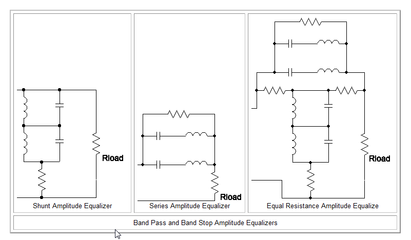
Here's the amp equalizers I have implemented in PCFILT. Look at the first two examples under amplitude equalizers. I have the three described as "lowpass equalizers"

http://www.filter-solutions.com/passive.html

The second set described as bandpass equalizers look interesting. For bandpass filters I would normally cascade two of the "lowpass equalizers". PCFILT can handle up to 10 as I recall.

I have never heard the term "inverted-half-sine/slope". Can you pint me to some examples? I'm guessing that refers to a single dip in attenuation maybe?

BTW: What were you unable to analyze? The equalizer example I posted earlier wasn't worth analyzing! :thumbsdn:

AL K.
 
"inverted-half-sine/slope"

Al,

The term "inverted-half-sine/slope" is for an EQ that can do both Negative/Positive Slope or One Peak (not Dip). I can manipulate it into many different shapes, here is the example of the EQ will do the same job as it shows on the website you provided.

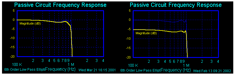
The picture shows a LPF before & after being equalized. Pay attention to the edge (roll off) of the pass band before and after to see how it dropped only 2 dB while the rest of the passband dropped 5 dB.:

EQ-Network2.gif


Here is the EQ (narrow band Inverted Half-Sine) that used to equalize the LPF:

EQ-Network4.gif
 
Krytar,

Ok.. That's just a fancy name for what I have always done. It's just a series "tank" with a resistor around it is sereis, or a parallel "tank" with a resistor in sereis connected in shunt. The fancy circuit is just a constant Zo version of the same thing. It's what that web site calls "lowpass equalizers".

Al K.
 
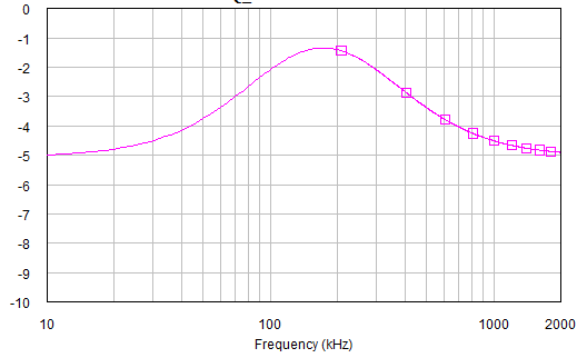
From that same EQ, by changing the L/C ratio , while maintaining the same level of attenuation (means didn't change the resistor values), A broadband Half Sine (look like a mountain) EQ is obtained. Use this to equalize "dips" or "valleys" of the response:

EQ-Network5.gif


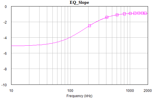
With that same EQ & move the resonance around, now we can obtain some negative slope response:

EQ-Network3.gif


All of the above can be accomplished with one L/C network & 2 resistors, while maintain constant impedance across the frequency range, not as complicated as shown in the website:


EQ-Network1.gif


Hence, the EQ can be called "Slope" (either "positive" or "negative", depends on which side of the mountain to be used) or "Inverted Half Sine" (or just "Half-Sine", up to the consumer :D)
 
Krytar,

From just looking at the more complicated networks, I think they will yield two humps. That's one for each corner of a bandpass. I have always just used two discrete networks instead. I think those would actually have less parts that two discrete EQs.

Al k.
 
Status
Not open for further replies.
Back
Top Bottom