• Please note that Audiokarma will be offline briefly for updates early on Monday morning, September 28th.

Klipsch Jubilee Crossover Network

Status
Not open for further replies.
Eq

It' so cumbersome. We can reduce half of the components to make it work the same. With that structure, I can have 2 humps & 2 dips at different frequencies.

2-hump network is much simpler than that. :D. Just did one for a wide band (2-18GHz) Radar Detection System to flatten a lumped element Bandpass filter (.5 dB window across the passband).
 
Krytar,

You would think all those parts would give you some advantage! I need to do a lot more fiddling with equalizer to really use them to advantage. For some reason, K&L doesn't use see them very often. I think the last time I did anything like that was to just stuck a second order all-pass group delay section in the middle of a passband to flatten the top a bit. Their natural component loss peaks near the group delay peak. The last actual amplitude equalizer I remember being involved with was years ago!

BTW: I finally got the added capability of equalizing disk file data working in PCFILT. I have it well implemented into the actual equalizer design module but its operation in the actual analysis is a bit crude. It works but I may not document that feature. In the equalizer module it also allows delay or amplitude data keyed in manually to be edited. That is a goody I had in the old DOS version but never put back in the Windows version. I have gotten away with it because you ALMOST always equalize data from the analysis of the filter you are equalizing.

Al K.
 
Eq

Al,

Equalizers come with many different sizes & shapes. I went back to check on model number with the old company, where I designed & built EQs. I found out that I had designed more than 400 model of equalizers for the duration of 7 years.

Those were stand alone equalizers to be used mostly to equalize the high power Microwave Helix Tubes (TWT), Cable Loss, and fine grain adjustment. Most of them were absorptive distributed EQs; some had mechanical coupling structure to create fine grain adjustment (Cavity & waveguide EQs). Very small portion used L/C network... Later I use the 2 humps network to flatten BPF in bigger system design, and also microstrip & thin film distributed network EQs for system use.

I wrote my EQ program use QBASIC for Microwave EQ Network. It doesn't run on later Windows program. Now, I design mostly by hand & use simulator to check the performance. I don't have time to re-write it since I don't have much use of it.

For other filters, I have a proprietary program (in DOS) to do both Lumped Elements & Comb Line design. The program was written based on George's book. It works very well. I use S/FILSYN mostly for complicated Multiplexer designs only.
 
Krytar,

I don't remember using QBASIC. I started out using MS BASIC and later Borland TURBO BASIC. I do everything in ANSI "C" these days. I wouldn't think modifying BASIC source code for modern systems wold be too difficult. I still have the Borland version running here for hacking old programs when I need to. It seems to run ok under W98 and XP emulated DOS. The problem I have is that I am still addicted to a shareware DOS word processor called PCWRITE. I use it for virtually everything but the PCFILT users guide. It works fine under W98 but has all sorts of trouble under XP. That's the main reason I'm still using W98!

Al K.
 
Krytar,

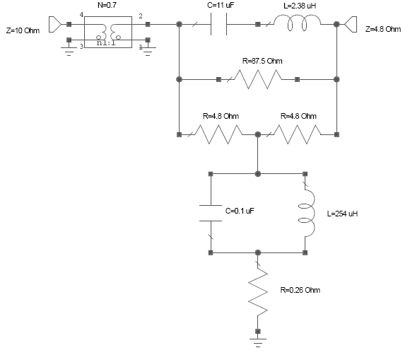
OK.. Here is my first feeble attempt at an equalizer for my Jub network with the modified PCFILT. The element values are not wonderful at all. The transformer boosts 4.8 Ohms up to 10, which seems to be the average Zo of the K69 driver. The autoformer with a turns ratio of .7:1 (1.4:1) give it about a 3 dB boost. The flatness is about +-3 dB out to 20 KHz. it's using only a single equalizer section.

Any suggestions?

Al k.
 

Attachments

  • Eq_try1.gif
    Eq_try1.gif
    32.6 KB · Views: 19
I've tried to keep up. I can't talk the language but have an interest.

Krytar, so up to this point, do you have a recommended EQ network? IOW....if you owned the speakers and where going to build a passive.....what approach/schematic would you use? If you already posted it...I must have overlooked it.

Or would you need the actual speaker to gather further information.

I have built and heard Al's ESN jub original design on a top horn that doesn't require EQ. I think it works great. I later purchased the K69/K510 horn (smaller version....not K402) and had ALK play with it before I ever had a chance to mess with it. I unfortunately don't even have the 510's hooked up right now and someone else has my Jub clones with AL's original ESNjub design.

Anyway...I may venture into playing with passives again if I decide to have some more jubilees sitting in front of me.

Ohhh...I see ALK posted as I was.....let me check that out.

jc
 
ALK's EQ

Al,

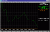
Is GREEN CURVE the transmission plot of the network above in your PCFILT?

If YES, then your PCFILT is either a "out of this world" program or it has serious problem.

The network you have is a slope equalizer where the top L/C series will determine the high end lowest point, and the shunt tank is using to set at the lowest frequency point to match out the entire frequency band. This is a typical broadband negative slope EQ. I assume the Xformer is for impedance transformation.

I don't know how can you get all the zig-zag performance out of the 2 resonators circuit.

Please confirm if my ckt layout is the same as your EQ on PCFILT:

jube_eq1.gif
 
JC

....if you owned the speakers and where going to build a passive.....what approach/schematic would you use?

I'll use the diplexer approach to build 2 separate net works: one for the low Xover freq (500Hz), or for the higher freq (5800Hz). then connect them together. With these network, I'll have constant impedance Zo, and also steep slope/octave, thus more BW & smoother sound.

...If you already posted it...I must have overlooked it.

I did post the schematic & data, but had to remove due to violation of my company policy. :yes:

Or would you need the actual speaker to gather further information.

I would rather have the measured data from manufacture of the speakers (all drivers) to see the appropriate approach
 
Krytar,

You have the equalizer schematic correct including the transformer. It was picked to change 10 Ohms down to 4.8 Ohms and boost the level by 3 dB at the same time.

The green plot is forward attenuation. It looks so rough because it has the curve posted by DeanG added to the response. That's the new feature I have been working on for the las couple of days. Analysis points lying between the data points are determined by linear interpolation. It only has 27 points taken from the curve:

600,3
700,2
800,2
900,1.9
1000,1.6
1500,0
2000,4
2500,5.4
3000,4.5
3500,4
4000,8
4500,11
5000,11.7
5500,11
6000,10.6
6500,10.6
7000,11
7500,10.5
8000,9.5
8500,8
9000,8.5
9500,10
10000,10
13000,6
15000,10.5
18000,11
20000,15

Al K.
 
Krytar,

Both the L/C circuits in the series and parallel legs are resonant at 31.115 Khz. I think they are there to complement each other so as to cancel each other yielding a constant impedance. I think the L/C ratio is what determines the correction bandwidth. My gut hunch is the two are the "dual" of each other but I haven't got the gumption to check if it really is! :boring:

AL K.
 
Al,

Without your comment, I'm totally lost when I looked at you curve. Next time add some comments to the plot so we know what we're looking at.

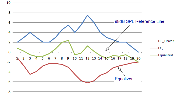
The equalizer didn't do much to Dean's curve. Remove Dean's number from the plot then you'll see what your real EQ look likes.
 
Krytar,

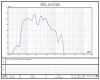
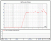
Here's the plot with the curve data removed. It's the curve of the equalizer only.

I'm so used to looking at those PCFILT plots I just take them for granted! Personally, I can't tell a blasted thing form looking at the equalizer curve alone. I need to see the equalizer response added to the curve of the object being equalized. That should be a straight line. To make Dean's curve look like a nice curve would take about 100 points. That isn't practical. All you need to see what is going on is the extremes of the curve to be equalized. That is what you are looking at.

Al K.
 

Attachments

  • Eq_only.gif
    Eq_only.gif
    17.2 KB · Views: 14
Krytar,

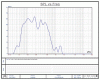
Here is the plot of the K69 driver alone (Dean's curve). Remember, it is only 27 data points on a linear x axis (frequency). His curve was on a log x axis. It will not look pretty unless I waste a lot of time keying in extra data points off the curve.

BTW: To explain those PCFILT plots a bit: All the information about scale factors and the reference line (top) are tabulated to the right of the plots. The color of the text corresponds to that of the plot. There is a dotted white vertical line that is the "marker". It can be moved right or left and the tabulated data shows the information about each curve where it crosses the marker. The marker is all the way to the left in this particular plot and sitting at 2000 Hz in the previous one. It would be obvious if you used it rather then just looking at screen captures. All the scale factors are automatic and are shown in the classic 1-2-5 sequence.

AL K.
 

Attachments

  • K69_cv.gif
    K69_cv.gif
    17.2 KB · Views: 7
Dean's plots

Dean posted 2 plots: one from 1KHz to 20KHz, and another set from 50Hz to 2KHz (one has a 1.5 KHz Strap).

I'd like to know is are these 2 curves separated by a crossover, then what is the crossover frequency? is it at 500Hz as a guess from the chart with 1.5KHz Strap?

If they are 2 separate curve (from a crossover) then it's very easy to design 2 simple system to equalize them.

Does anyone has all the info/data on the drivers used in the Jubilee? or please point me to where can I get the info.
 
I'm not always the sharpest knife in the drawer, but please take the time to read my posts.:) I've posted 4 plots in this thread.
The first plot in the K-69-A driver mounted on the K-402 horn. The response is raw, that is, out-of-network or no network.

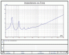
The second plot is the same driver and horn, but being driven with the Delgado designed passive network.

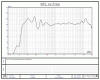
The last two plots were in the same jpeg. The first is the LF section raw response, the second is with the network.

Delgado's network produces an acoustic crossover of 550Hz. I don't know what the actual electrical crossover is.

Does anyone has all the info/data on the drivers used in the Jubilee? or please point me to where can I get the info.

The only data that matters is what the driver is doing on a specific horn. The raw driver data won't help much. Specifically, what do you need?
 
Here is all posted from Roy. Dean has these too. I'm just gonna vomit up what I have.

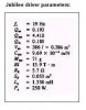
The T/S paramenter is of one woofer

jc
 

Attachments

  • JUBLFRAW.gif
    JUBLFRAW.gif
    45.7 KB · Views: 19
  • JUBLFNETZ.gif
    JUBLFNETZ.gif
    45.4 KB · Views: 16
  • JUBLFNET.gif
    JUBLFNET.gif
    45.9 KB · Views: 21
  • JUBHFNETZ.gif
    JUBHFNETZ.gif
    44.3 KB · Views: 18
  • JUBHFNET.gif
    JUBHFNET.gif
    44.8 KB · Views: 27
  • JUBLFRAWZ.gif
    JUBLFRAWZ.gif
    45.2 KB · Views: 12
  • JUBNET.gif
    JUBNET.gif
    45.3 KB · Views: 21
  • JUBNETZ.gif
    JUBNETZ.gif
    45 KB · Views: 16
  • K-31.jpg
    K-31.jpg
    11.6 KB · Views: 25
Yikes, I didn't know the forum lets you post that many files. Thanks JC, that saved me some work.
 
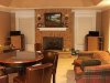
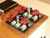
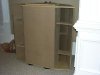
Ah just for fun...here is some pics of my unfinished jub clones with Altec 511, Al's original ESN w/o EQ.

jc
 

Attachments

  • Jubilee-ESNALKJUB-902-511.jpg
    Jubilee-ESNALKJUB-902-511.jpg
    70.7 KB · Views: 54
  • ESNALKJUB-finished-3.jpg
    ESNALKJUB-finished-3.jpg
    103.3 KB · Views: 50
  • 01010014-small.jpg
    01010014-small.jpg
    52.5 KB · Views: 46
Here is the initial design of the Jubilee network.

Jube_02.gif


And here is the High frequency equalizer network (K69 + 510):

Jube_EQ1.gif


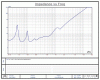
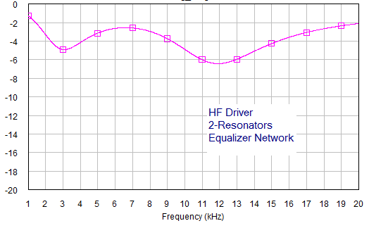
Simulated Data for the 2-Resonators Equalizer Network:

Jube_EQ_HF1.gif
 
Status
Not open for further replies.
Back
Top Bottom