

You are using an out of date browser. It may not display this or other websites correctly.
You should upgrade or use an alternative browser.
You should upgrade or use an alternative browser.
Klipsch Jubilee Crossover Network
- Thread starter krytar
- Start date
- Status
- Not open for further replies.

krytar
Member
AL,
Resonance for both of of your L/C (series & shunt) are not existed. L/C ratio of both are extreme; either dominated by the series capacitor or shunt inductor. The series cap became a blocking cap, shunt L became a DC choke. Both of them doing the same thing, then the resistors network just simply add attenuation to the circuit; hence, the plot.
Resonance for both of of your L/C (series & shunt) are not existed. L/C ratio of both are extreme; either dominated by the series capacitor or shunt inductor. The series cap became a blocking cap, shunt L became a DC choke. Both of them doing the same thing, then the resistors network just simply add attenuation to the circuit; hence, the plot.
Krytar,
First off, before I read any of your last posts in detail, I apologize for getting so mad. I should have waited a while before mouthing off. I think it's because your English is not perfect (as if mine was). I suspect English is not your first language now that I know you name rather then just "Krytar". It results in you seeming to have a lack of tact. Trying to communicate using text without the benefit of vocal inflections makes it difficult to begin with! It's never easy to tell somebody that they are wrong without offending them. I think that's why these things were invented--> :tears:
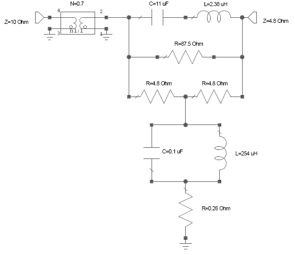
The reason your analysis of the constant Zo equalizer was wrong is because you probably have the transformer reversed. Try a ration of 1/.7 (1.43). The return loss should be perfect.
Al K.
First off, before I read any of your last posts in detail, I apologize for getting so mad. I should have waited a while before mouthing off. I think it's because your English is not perfect (as if mine was). I suspect English is not your first language now that I know you name rather then just "Krytar". It results in you seeming to have a lack of tact. Trying to communicate using text without the benefit of vocal inflections makes it difficult to begin with! It's never easy to tell somebody that they are wrong without offending them. I think that's why these things were invented--> :tears:
The reason your analysis of the constant Zo equalizer was wrong is because you probably have the transformer reversed. Try a ration of 1/.7 (1.43). The return loss should be perfect.
Al K.
Krytar,
I am aware that the element values are not practical. All the parts are to make it constant Zo. That was the reason for trying that topology. I was hoping that, with a match Zo, I coud use the transformer somehow to give me gain. That's not going to work. Moving the resonant frequency of those "tanks" down might help the value spread, but probably not enough. I was mainly experimenting with the new capability in PCFILT of adding in the data from a plot.
I can't see how any passive network is going to raise the high frequency rolloff of that K69 driver to 105 or 110 db SPL. All that can be done is to knock the high sensitivity low frequency range down. Lowering the Zo up high could do it to draw more power from the amp, but the Zo is too low already at 4.8 Ohms.
Al K.
I am aware that the element values are not practical. All the parts are to make it constant Zo. That was the reason for trying that topology. I was hoping that, with a match Zo, I coud use the transformer somehow to give me gain. That's not going to work. Moving the resonant frequency of those "tanks" down might help the value spread, but probably not enough. I was mainly experimenting with the new capability in PCFILT of adding in the data from a plot.
I can't see how any passive network is going to raise the high frequency rolloff of that K69 driver to 105 or 110 db SPL. All that can be done is to knock the high sensitivity low frequency range down. Lowering the Zo up high could do it to draw more power from the amp, but the Zo is too low already at 4.8 Ohms.
Al K.

Coytee
Super Member
Krytar,
First off, before I read any of your last posts in detail, I apologize for getting so mad. I should have waited a while before mouthing off
Ahhhhhh, the softer side of Al.... :thmbsp:

Guys,
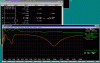
Here's the entire thing all together. The plots is of my Jubilee network plus Krytar's latest equalizer plus the data from the K502 plots all added to together. I changed one resistor form 5.6 to 4.7 Ohms. It made very little difference and was not critical. It looks pretty good having about a +- 5 dB response.
I also tried adding a transformer (.7 / 1.4 ratio) to match 4.8 Ohms to 10 Ohms between the output of the equalizer and the driver. It didn't do much! I am concerned that the woofer level will not match the highs though.
BTW: I still think a 3-way system is a better deal. You get a flat response and well over 100 dB sensitivity too. The total acoustic power into the room may move up and down between driver ranges, but I personally think it's a better compromise.
Al K.
Here's the entire thing all together. The plots is of my Jubilee network plus Krytar's latest equalizer plus the data from the K502 plots all added to together. I changed one resistor form 5.6 to 4.7 Ohms. It made very little difference and was not critical. It looks pretty good having about a +- 5 dB response.
I also tried adding a transformer (.7 / 1.4 ratio) to match 4.8 Ohms to 10 Ohms between the output of the equalizer and the driver. It didn't do much! I am concerned that the woofer level will not match the highs though.
BTW: I still think a 3-way system is a better deal. You get a flat response and well over 100 dB sensitivity too. The total acoustic power into the room may move up and down between driver ranges, but I personally think it's a better compromise.
Al K.
Attachments

jwcullison
Active Member
very nice. Will look at this some more to see if I can visualize the build.
jc
jc
jwcullison
Active Member
Al.
Can you post the "schematic editor" window so that I can see the bottom half.
thanks.
jc
Can you post the "schematic editor" window so that I can see the bottom half.
thanks.
jc
JC,
I wouldn't build anything seriously yet. That combination I just posted is nothing more than an academic exercise! I would wait a while for a few more ideas before I started building. You could try patching the equalizers into networks you already have by making the equalizers on a separate board from the network so you experiment with them. I'm pretty happy with the crossover network I posted but I think the EQ needs more thought. Keytar's EQ flattens out the response, but I'm still hoping one can be made that is constant impedance. After all, that's my thing you know!
The bottom half of the schematic is simply my new design for the Jube network. Just below the EQ is the network high filter.
Al K.
I wouldn't build anything seriously yet. That combination I just posted is nothing more than an academic exercise! I would wait a while for a few more ideas before I started building. You could try patching the equalizers into networks you already have by making the equalizers on a separate board from the network so you experiment with them. I'm pretty happy with the crossover network I posted but I think the EQ needs more thought. Keytar's EQ flattens out the response, but I'm still hoping one can be made that is constant impedance. After all, that's my thing you know!
The bottom half of the schematic is simply my new design for the Jube network. Just below the EQ is the network high filter.
Al K.
jwcullison
Active Member
Yes Al. I'm just trying to visualize the build.
I'm a little confused with the "schematic editor". I'm sure I have it wrong but the "in and out" looks inversed from what Krytar posted. That is why I was hoping you could post the window with the schematic so I could see the bottom of the window.
Yes.....For some upcoming projects...I could do another ESNjub (newer one) of yourse and tryout EQ's. The EQ builds aren't as pricey...so i'm sure I could be the trial and error.
jc
I'm a little confused with the "schematic editor". I'm sure I have it wrong but the "in and out" looks inversed from what Krytar posted. That is why I was hoping you could post the window with the schematic so I could see the bottom of the window.
Yes.....For some upcoming projects...I could do another ESNjub (newer one) of yourse and tryout EQ's. The EQ builds aren't as pricey...so i'm sure I could be the trial and error.
jc
JC,
Yes keytar's EQ is reversed. This shouldn't make any difference. What bothers me is the impedance level of the EQ. He didn't specify what it was. I have it stuck into a 4.8 Ohms system and terminated in 10 Ohms. That should be incorrect. That's why I tried to add in a transformer to match 4.8 ohms to 10 Ohms. It didn't do much! That's why I'm hoping for a constant impedance eq. The constant Zo equalizer is the one with all the parts and extreme value spread. It's what is sometimes called a "Rube Goldburg"!
I have attached the entire schematic.
Al K.
Yes keytar's EQ is reversed. This shouldn't make any difference. What bothers me is the impedance level of the EQ. He didn't specify what it was. I have it stuck into a 4.8 Ohms system and terminated in 10 Ohms. That should be incorrect. That's why I tried to add in a transformer to match 4.8 ohms to 10 Ohms. It didn't do much! That's why I'm hoping for a constant impedance eq. The constant Zo equalizer is the one with all the parts and extreme value spread. It's what is sometimes called a "Rube Goldburg"!
I have attached the entire schematic.
Al K.
Attachments

jwcullison
Active Member
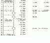
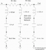
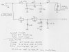
Great. I hope I have this correct. The first image is your last one which is the combination of your latest ESNjub and Krytars latest EQ. The other two are Krytars last EQ suggestion and your ESNjub.
So this is what we are working with....right?
jc
So this is what we are working with....right?
jc
Attachments
JC,
Yes, you have it straight.
The questionable part is connecting them together.
The 12 Ohm resistor I show on the hand drawing should be left out.
The equalizer can be reversed but I don't know if it should go in a 4.8, 8.0 or 10.0 environment. The K69 is roughly 10 Ohms and my network is 4.8 Ohms.
Al K.
Yes, you have it straight.
The questionable part is connecting them together.
The 12 Ohm resistor I show on the hand drawing should be left out.
The equalizer can be reversed but I don't know if it should go in a 4.8, 8.0 or 10.0 environment. The K69 is roughly 10 Ohms and my network is 4.8 Ohms.
Al K.
jwcullison
Active Member
JC,
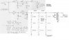
You almost have it. Like you said, remove the 12 Ohm resistor AND the transformer is reversed. This time it's wire step-UP rater than step-down. The input from the network goes to 4 and the driver to 5. 0 is grounded.
Al K.
You almost have it. Like you said, remove the 12 Ohm resistor AND the transformer is reversed. This time it's wire step-UP rater than step-down. The input from the network goes to 4 and the driver to 5. 0 is grounded.
Al K.
jwcullison
Active Member
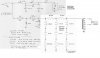
OK. Well the good thing here is that I can visualize it. I removed the 12 Ohm resistor.
I don't know how to manipulate the "symbol" for transformer but I gave it a shot. Is the mid driver as usual NOT grounded with common ground?
So will I as usual be able to have adjustable tap settings for alternative dB output.
I guess the way to do this is to make the ESN w/o the autoformer. Then make a seperate EQ board with the autoformer or just put the autoformer on a third board like your tweeter attenuators.
jc
I don't know how to manipulate the "symbol" for transformer but I gave it a shot. Is the mid driver as usual NOT grounded with common ground?
So will I as usual be able to have adjustable tap settings for alternative dB output.
I guess the way to do this is to make the ESN w/o the autoformer. Then make a seperate EQ board with the autoformer or just put the autoformer on a third board like your tweeter attenuators.
jc
Attachments
jwcullison
Active Member
Krytar. If you are still around and still interested in this stuff, would you like to take a crack at an EQ for the K69 driver on the K510 horn. Same driver but smaller horn.
The two uploaded images showing raw frequency response and impedance are a few pages back.
I think Al posted his earlier in this thread.....or maybe he didn't. I'd have to look back.
jc
The two uploaded images showing raw frequency response and impedance are a few pages back.
I think Al posted his earlier in this thread.....or maybe he didn't. I'd have to look back.
jc
jwcullison
Active Member
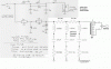
thanks Al. OK so it is fixed tap settings.
On your redraw...there are two #5's on the diagram. I'm assuming the bottom one is supposed to be 0.
Thanks again Al. I need to try this out.
jc
On your redraw...there are two #5's on the diagram. I'm assuming the bottom one is supposed to be 0.
Thanks again Al. I need to try this out.
jc
JC,
Yes, I forgot to change that 5 on the bottom. It's 0.
BTW: I think I'm on to something that might be an improvement. By raising the impedance up then back down with two transformers I can make the "Rube" constant impedance equalizer practical. I can also reduse its complexity to two cap, two inductors and 2 resistors. The kicker is TWO transformers! I post the idea when (and if) I get a design that looks promising.
Al K.
Yes, I forgot to change that 5 on the bottom. It's 0.
BTW: I think I'm on to something that might be an improvement. By raising the impedance up then back down with two transformers I can make the "Rube" constant impedance equalizer practical. I can also reduse its complexity to two cap, two inductors and 2 resistors. The kicker is TWO transformers! I post the idea when (and if) I get a design that looks promising.
Al K.
- Status
- Not open for further replies.