• Please note that Audiokarma will be offline briefly for updates early on Monday morning, September 28th.

Klipsch Jubilee Crossover Network

Status
Not open for further replies.
jc,

Here's a real Rube delight! It's for the K510 horn and uses 2 constant ZO equalizers and two transformers. Three resistors are NOT actually there. The one marked 1e+06 at branch number (on the left) 5 is open circuit. The other two are 0 Ohms at branch numbers 10 and 18. I forgot to round of the cap at branch 16. It should be .92 Uf if you can get that value. 1.0 Will do.

The response is +-5dB up to 20 Khz. Impedance match is 1.5:1, which is Ok.

AL K.
 

Attachments

  • dual_eq.gif
    dual_eq.gif
    69.9 KB · Views: 18
Al,
When you guys get done, can you please send me an email with the changes I need to make to my Jub clone networks. I am still running the original + ES5800 in 3 way.

Thanks
 
Mark,

I'm not sure I will EVER be done! I just picked up a book that has more information on constant impedance equalizers than I have had. There is another version that has the opposite response than the one I have been using by reversing the parallel and series L-C "tanks" in the positions around the resistors. This will put the resonance down low making the L-C values much larger. I need to look into this before I finalize any design. For me, this usually involves computer programing and takes a while! In other words, don't hold your breath waiting for me to get off my butt! I am behind on building networks big-time! If you interested in the network I posted earlier on this thread, it is not likely to change and you could build it as is. It's the equalizer that's up in the air. I am a novice at those things and I need to reinvent the wheel to learn about them. Just figure on building that on a separate board.

AL K.
 
yea Mark.

You have the essentials already. You may have to change the swamping resistor and that is about it. I wouldn't alter that ESN jub crossed at 600Hz.

You have THE first custom ESN for the jub! In fact...it may be the first one made besides the one Roy put together at Hope in 2005....mono.

The extra board for the EQ should be easy to do....it also shouldn't be that expensive either.

You have alot of flexibility with your setup as you can change the top horn driver at any time while keeping the ESN in the mix.

jc
 
Al. Thanks for that K510 schematic. Any chance you could post that w/o the "Analysis results" window ontop. I have to draw it out to understand it.

Here is the final on the jub-K402 ESN with EQ. I put the "0" where it belonged.

Thanks Al.
Krytar.....where are you?

jc
 

Attachments

  • Jube-ESN-EQ-test3.jpg
    Jube-ESN-EQ-test3.jpg
    46.8 KB · Views: 34
JC,

Your latest drawing looks correct.

The last eq I posted is just me thinking out loud! You don't want to build that one either! I want to investigate what's called the bandstop equalizer. The one I was using is the bandpass type. I need some time to investigate this before I actually say a design is worth building. As of right now, I suggest you go for Krytar's equalizer. It's not constant impedance, but I think because it's so much simpler it's more practical.

Al K.
 
yea Mark.

You have the essentials already. You may have to change the swamping resistor and that is about it. I wouldn't alter that ESN jub crossed at 600Hz.

You have THE first custom ESN for the jub! In fact...it may be the first one made besides the one Roy put together at Hope in 2005....mono.

The extra board for the EQ should be easy to do....it also shouldn't be that expensive either.

You have alot of flexibility with your setup as you can change the top horn driver at any time while keeping the ESN in the mix.

jc

I haven't read that closely because you guys are out there on me anyhow. I'm just wondering.....do I have the latest Jub ES600 without EQ....or is there an improved version of the same thing I have (added inductor or something like that?).
I just want to be sure that what I am using for now is the latest. If I have to make a mod....no problem that's fine.
 
Yes. Al has updated the network. He can tell you how much audible difference there may be. It may not be worth the change as you hace some expensive caps on yours.

I have uploaded the original and the latest. They have already been posted in this thread and I had to give them a different file name in order for the server to let me repost.

The first attachement is yours...the one I made....original design.
The second one is the latest....never been built as far as I know.

I did curves on the one I built. The XO is almost right on the 600Hz mark. The two drivers together made a smooth transition.

Mark...for some reason I can't upload right now. I'm about to email them to you.

jc
 
Mark,

The new design adds an inductor right where the woofer is connected. This was to increase the apparent woofer voice coil inductance. It allowed the entire thing to be redesigned. The result is deeper ultimate rejection to the driver that is NOT making a sound at a given frequency. The difference in sound should be subtle, just a less driver interference. I think it added nearly 10 dB if I remember right.

BTW: initial experiments with the bandstop constant impedance equalizer shows that it's just a different bag of worms then the bandpass type! I'll know more later.

Al K.
 
Guys,

Progress report:

After fooling with the "bandstop" equalizer for a while I have concluded it's worse than the other one (bandpass type). It's because it gives you huge insertion loss. There are two more types of constant impedance equalizers I will investigate next. They are the lowpass and highpass types. These are simpler than the other two having two fewer parts and look to be more promising for this application. BTW: Implementing these equalizers into my software (PCFILT) and using the Klipsch driver responses as a test bed is kill two birds with one stone! I like it! :D

AL K.
 
Guys,

Here's the results of a lot of program expansion to PCFILT. This is the
equalizer I propose for use with my second Jubilee crossover and the K510 horn.

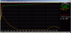
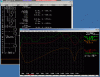
The attached plots are of the network + equalizer + K510 curve. The other
plot is of the network + the equalizer withOUT the K510 response.

This equalizer is constant impedance and seems to yield +-5 dB flatness from
600 Hz up to 20000 Hz. The insertion loss is about 0.5 db at 18 Khz.

All the part values are off the shelf items from Solen except the inductor at
branch 13 (.053 mHy). This can be made by winding two layers of #16 wire on
a 1.5 inch OD PVC pipe. The winding will be 1.63 Inch long. It can be of solid
wire but Litz is better. You can get the wire by buying a litz wire inductor
from Solen and unwinding it.

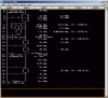
The resistor at branch 9 marked 1e+08 is an open circuit. Just leave it out.
1e+08 is the computers way of saying it 10 million ohms! Gone!

The transformer is the Universal transformer #3619 connected in reverse. Tap
4 goes to the network output and the equalizer side is connected to tap 5.

If anyone is confused by the computer schematic drawing, let me know. I will
draw it in a more familiar format.

AL K.
 

Attachments

  • Clip1.gif
    Clip1.gif
    65.3 KB · Views: 22
  • Clip2.gif
    Clip2.gif
    41.6 KB · Views: 19
Yep. That did it.

It might take me a little time to digest that EQ part. Looks complicated for my skill level. I think I just need to draw it out.

jc
 
Yea...I need to just draw it out.

What I will probably do is build your newest ESN first. Run curves and such. Then try out the EQ part later.

I'm hoping I can use 2 K-31 E's loaded in an exponential horn wired parallel in a different type cabinet than the jubilee.

jc
 
I've said this to you many times, the only thing that matters is the acoustic response.
It's not just you saying it either.

What in the world is this obsession with presenting a resistive load to the amp? I think some people need to read up on the non-linear behavior of loudspeakers. There's some interesting conclusions that cause a lot of problems with these fancy networks...and I say that knowing full well how cool these networks appear from an RF designer perspective. The literature is out there and free for anyone honestly interested in learning.
 
Who,

Your opinion is well known and noted. My opinion is that constant impedance represents the mark of a more advanced design. You can believe anything you like.

You say "why?", I say "Why not?". My answer to "why not?" is because you don't know how! It's often called a cop-out!

AL K.
 
jc,

"I'm hoping I can use 2 K-31 E's loaded in an exponential horn wired parallel in a different type cabinet than the jubilee."

DAH! I don't follow you. Wouldn't building an "exponential horn" be just as much trouble as building a Jubilee clone? :confused:

AL K.
 
After the wood is cut, I can assemble one jubilee clone in about two weeks.

I have drawn up several plans that utilize dual K-31's in a smaller sized application. The throat and back chamber volume will be calculated just as Roy's and PWK's AES paper.

I am curious on how K-31's would sound in a straight Tractrix flare with an Fc of 70hz. This could be used as a center channel or similar application such as you would use a la scala. I have several varieties of an exponential bass horn with only one fold with an Fc of about 70Hz like the la scala.

The Jubilee project was great but was a real pain to move around and test due to its weight. I was interested in a smaller scaled bass horn for now.

jc
 
Status
Not open for further replies.
Back
Top Bottom