• Please note that Audiokarma will be offline briefly for updates early on Monday morning, September 28th.

Klipsch Jubilee Crossover Network

Status
Not open for further replies.
LF Equalizer

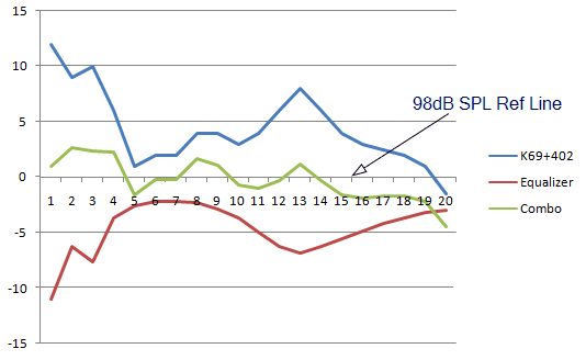
Here is the LF equalizer plots
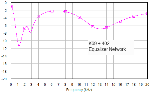
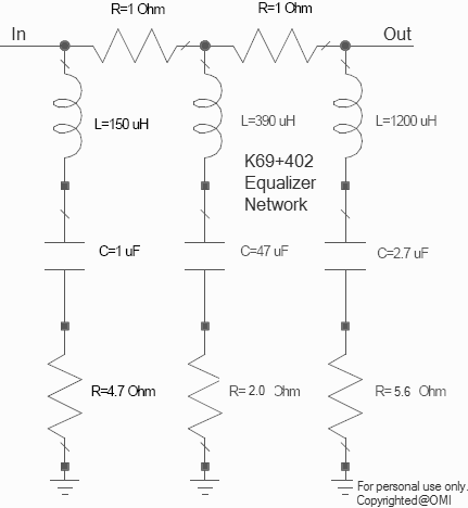
1) LF 3-Resonators Equalizer Networks
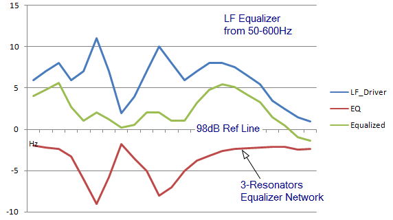
Jube_EQ2.gif


Simulated data of the equalizer network:
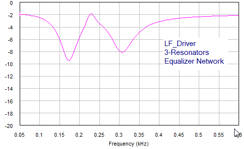
Jube_EQ_LF1.gif


Here is the circuit:

Jube_LF_EQ_3.gif


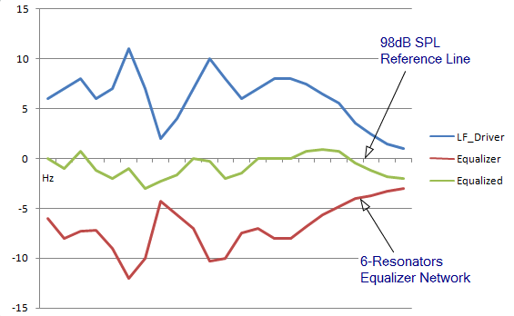
2) More complicated Equalizer (6-Resonators Network) will do some serious equalizing work :D:

Jube_EQ3.gif


Simulated data for the above Equalizer:
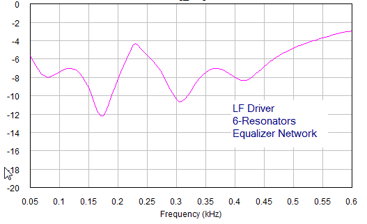
Jube_EQ_LF2.gif


Here is the circuit:

JubeLFEQ6.gif
 
Krytar,

Here's all the information I have.

The Jubilee woofer has two drivers in parallel, so the Zo is low. JC measured it to be 4.8 Ohms in series with 0.6 mHy.

The plot is of the K69 on a K510 Horn. I think it will be similar on the K402 horn. The frequency response is different though.

Al K.
 

Attachments

  • K69_zo.jpg
    K69_zo.jpg
    127.1 KB · Views: 27
Krytar,

You accurately redrew the circuit of the equalizer I suggested but didn't bother to comment on it. Should I assume you don't like it? All you have done so far is criticize my plots showing the manually keyed in data taken from the K69 plot Dean posted. You have also not provided me with any networks to look at. Even before your employer made you remove some of your plots there was nothing there to analyze, just L1, L2, C3, etc. You have sent me nothing by email or private message either. The plots you posted above look nice but mean nothing! Are you sending this stuff to Dean and JC but not me?

Should I go away?

AL K.
 
I don't have anything from him Al, and I'm pretty sure JC doesn't either. Right, the plots are fun, but that's about it. Now, don't go away, the world is a little less interesting when you're not around.:)
 
Dean,

I will be here until it gets to be a total waste of time to remain. So far nothing of substance has been posted other than my design for the Jubilee network. I am learning nothing and am starting to get very frustrated at the lack of anything but a lot of pretty curves of some unknown networks.

Keytar,

If you can't give us any designs, either privately or publicly, you are just blowing smoke up our posteriors. I suggest you either get permission from your employer to post real stuff or start doing this on your own time. There are no TWT amps or 30 GHz applications here meaning your employer will be loosing nothing. Remember that I too can post pretty plots of stuff you will never see. Part of the scientific method is publishing your data and conclusions for review by your piers.

Al K.
 
Al. Here is Roy's curve of the K69 and 510 horn.

jc
 

Attachments

  • 510-69.GIF
    510-69.GIF
    38.7 KB · Views: 27
  • 510-69z.GIF
    510-69z.GIF
    37.5 KB · Views: 16
So here is the K69 curve raw with the 402 ...I think Dean posted this.

jc
 

Attachments

  • JUBHFRAW.gif
    JUBHFRAW.gif
    44.9 KB · Views: 11
JC,

That's the first I have seen of the official response of the K69 + K510 combination. It looks close enough to the curve I made to make me happy! Their curve is much smoother, but the overall rolloff is very similar.

Sometime I'm going to try sticking data from that curve into my analysis along with several equalizers, including the one I suggest to you a while ago, to see how the combination looks. This is a new capability for my software and I need to prove to myself it's working right.

AL K.
 
Al,

Please don't rush to made any "rough" comments. This takes sometimes to design. I can't pull it out from the air. I just post the info very late last night (actually early in the morning). I need to sleep too :D and you don't want me to be trouble either.:no:

I'm awaiting for comments about it, then will send the info to anyone, who has a need to build for personal use. I'll send the info also to you for analysis. I can't post the circuit on the net for now, but will send it out privately.
 
ALK Equalizer

Hi Al,

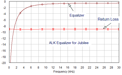
Here is the plot of your equalizer, you should get the same result on your PCFILT after you remove Dean's curve. A blocking cap would have done the same job, don't you think? :D:

Jube_ALK_EQ.gif
 
Krytar,

"I'm awaiting for comments about it"
Comments on what? You have posted noting but a curve! That's my comment.

"A blocking cap would have done the same job, don't you think?"
NO! I think NOT! Your plot of my EQ is wrong. VSWR is expressed as N:1. Not some number of DB. Besides, The VSWR on a constant impedance equalizer is 1:1. Where did you get -9 dB? WRONG! it should be off your graph at > 20 dB RETURN LOSS, not VSWR! Look at my plot (It's the BROWN curve). I suggest you put a blocking cap in your simulator and look at the "VSWR". If you have noticed, I am getting MAD, your right! I asked early on what circuit simulator are you using : Touchstone, SPICE, MW office? You didn't answer! Are you afraid to swap net lists by email?

Al K.
 
JC,

Here's the plot of the R-L-C equalizer I suggested to you months ago plus the curve of the K510 you posted. According to the computer the equalization didn't look to good. It had a downward droop as frequency went up. I fiddled the series 10 Ohm resistor up to about 27 Ohms and got a response of +-4 dB or so. The impedance is fair, but not wonderful at 12 dB return loss at 19 KHz.

The sensitivity is, of course, still as low as before (90-100 dB).

I am also not at all sure that matching the impedance with a transformer to kick the voltage up is going to buy anything as I suggest before. After all, a transformer cant add power. All it can do is reduce the Zo seen by the amp sucking out more power. To match the Zo may not do that. I am confused about that point.

Al K.
 

Attachments

  • K510_eq.gif
    K510_eq.gif
    36.2 KB · Views: 15
Thanks Al.

I follow your diagram. A simple circuit to build.

So sounds like we are still will a lower overall SPL with the EQ to match a bass reflex system and not a bass horn system.

Is this correct?

I have a little experiment coming up that I may be able to try this with.

Now......if I match this to the ESN700 (non-t), where would I need to place the Auto former ....I forgot.....after the Eq or before it?

Thanks

jc
 
JC,

For use with the ES700, the input resistor should be 10 Ohms to match 6 Ohms, The one I just posted was to work with the Jube xover (4.8 Ohms).

As to the xformer placement, I don't remember either! I think it was to match the levels. In that case, it could go either place. The only difference would be the swamping resistor. Again. I'm not sure. I am confused by all the variation and hypothetical situation that have gone by here lately!

Al K.
 
O that's right!

What was I thinking.

Well. I own 8 K31 woofers...new in box. I was hoping to build some dual woofer "straight horns" with an Fc of 80Hz. Just a fun project.....possibly to use for a center or surrounds.

jc
 
Krytar

That I can follow.

So what does that do to the overall SPL? I see the "combo" curve....is that "about" 3 dB down?

jc
 
AL,

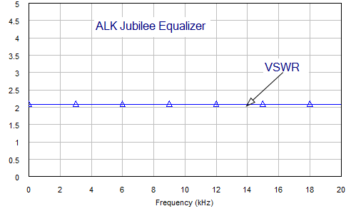
That was Return Loss, I corrected already. For any "real" engineer, we don't make a "dingdong" out of that :D. In dB we should understand that is return loss. Here is the VSWR from your circuit.

Jube_ALK_EQ_VSWR.gif


The plot came from your circuit. The result is straight out from a circuit simulator. I have nothing to do with it. If you "THINK" it's wrong then it must be the simulator, not me; I'm just the messenger :D. I ran your circuit after I laid it out & got your confirmation. My comment is from looking at the plot. Sorry if that ticks you, I'll change my comment if the plot come out differently:D. I checked the circuit using different programs & the result is the same :scratch2:.

Use your PCFILT and run the circuit by itself to confirm the result. The result should be the same. You need to remove the hand input data from the curve to see your circuit. Do that & put the plot up here for everyone to see then I have a case to complaint with the circuit simulator company:D. It cost over 100K with all the dingdongs 3D, 4D stuffs & can't do a simple circuit. :D

Look at your circuit & resonance frequencies of the resonators, I (NOT YOU) have no clue how it works with the Jubilee.
 
Krytar.

So with the way I'm reading this, the speaker SPL wil be around 98 dB?

Sorry...there is a rookie present.

jc
 
Status
Not open for further replies.
Back
Top Bottom