• The move to the new server is done. There are some software and database maintenance updates in process. This has us passing the hat around to help out. We appreciate any donations. Seriously, even a dollar helps. The payment page may be found here - https://www.audiokarma.org/support.html

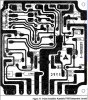
P750 Illustration

bibota

New Member
Hi all Marantz people,
I find it an absolute pain trying to make sense of this, so just wondering: has anyone got a better readable version?


P750 component locations L.jpg
 
Register to hide this ad
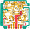
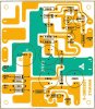
Here is a colorized version of the 2230 P750 board layout, done from a clean scan.
Wow, this is absolutely beautiful, many thanks runningdog. Such a difference!
Any chance of more of the same for other boards?

BTW, I got the transistors you suggested and have them on board now together with many other new bits.

What are you trying to determine?

During the last month or so I've been kept busy replacing bads on the P750. Something went wrong there and fried a whole bunch.
I may put it to the test today, with the Variac. Which again is a first, just bought it for this very project.
 
Every copy I have looks like that. Can't you just look at the power amp for the other channel?

Tom

I know Tom, I went far and wide myself looking for a better resolution and there were all identical; so glad to see runningdog's, can't have enough of it now.
I find that having a print of the layout as reference is very useful when identifying the points to be de-soldered on the back of the board.

On a related issue, I remember you making a comment somewhere about the diode attached to the heat sink. It is the only component I couldn't trace anywhere and I sort of went ahead hoping that the fault may be somewhere else.
If the functionality test proves that I didn't get to the bottom of the problem after all the new parts put in, there may be the case for me to replace the diode as well.
Any chance you could suggest a source please?
 
First thanks to Randy (runningdog) for the great colorized layout!

bibota,
The only place I know of to get the exact diode (SV-3A) that is used as the bias temperature compensation in the 2230 is from a donor Marantz. Models 1030, 1060 and 2230 use the same one AFAIK.

Tom
 
Really thrilled that I can myself have a contribution to AK. Minor one admittedly and a mere amendment to the hard work done by somebody else, but I'm rather proud of it anyway.

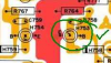
In the colorized version of the 2230 P750 board layout kindly provided by Randy, H753 should be facing like this:

upload_2017-1-7_18-30-53.png

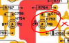
as opposed to this
upload_2017-1-7_18-40-41.png

Bringing the overall picture to this
upload_2017-1-7_18-28-58.png

Speaking of TO-92 transistors on this board: am I the only one finding that KSC2383 works much better than KSC945C for the H751? Although I've seen them both recommended for that position, KSC945C seemed to bring with it a sizeable loss in the mid to low range. Things come alive as soon as KSC2383 replaces it.
But of course, KSC945C does a perfectly decent job at H753.
 
Interesting. The recommendation I was given on my first 2230 was to use KSC1845 at H751. That's what I have always used. I may have to do a comparison next time.
 
The recommendation I was given on my first 2230 was to use KSC1845 at H751.
Were you replacing the transistor because it failed? Or is known to fail often? Or were you replacing some/all of the transistors? I'm trying to gauge if H751 should be replaced routinely during a rebuild.

Really thrilled that I can myself have a contribution to AK.
Thank you for the correction to the board layout and good catch! I just compared the updated document to a couple of amps and sure enough H751 goes the other way.

The colorized board layout comes from ak'r TimCartier and I agree it is awesome. And now even more so, thanks!
 
Were you replacing the transistor because it failed? Or is known to fail often? Or were you replacing some/all of the transistors? I'm trying to gauge if H751 should be replaced routinely during a rebuild.
I think on my first 2230, I got a parts list form MBuras and replaced everything on his list, which included H751. Since then, I have done a couple of others and only replaced the electrolytics. Right now, I'm leaving well enough alone in the way of semis on the power amps if everything adjusts out well.
 
I just finished a 2230 and here are some more cleaned up scans of the P400 and P800 boards that are clearer than the scans in the SM I have.. They were copied from other posts but I can't remember where so thanks should go to whoever uploaded them first.
P400 Tone and PreAmp Assembly.jpg P900 Power Supply.jpg
 
Back
Top Bottom