• The move to the new server is done. There are some software and database maintenance updates in process. This has us passing the hat around to help out. We appreciate any donations. Seriously, even a dollar helps. The payment page may be found here - https://www.audiokarma.org/support.html

alexhastings

Active Member
After discovering a failed PA3004 chip on my SA-7700 rebuild, and paying $35 for a single replacement, I asked @merlynski to help me design a PCB substitute, so we can all keep rehabbing these old units without paying exorbitant prices for new "old stock" chips.

Our design goal was to replicate all functions of the original chip, allowing the board to be used as a drop-in replacement in all use cases, in as small a package as possible.

The PA3004 is a speaker/output stage protection circuit in certain Pioneer amps and receivers which includes; DC deviation, B-/+ detection, AC detect, discharge/switching and power muting.

I think we have succeeded admirably, and we're happy to offer the full gerber, design and BOM files here so that any one can use them. I created a small website with info and files for download here:

https://guerillavending.com/alex/PA3004/

I think we succeeded in designing a circuit that would replicate all functions of the original chip, and the price is a significant improvement as well - when building 10 at a time, the cost is about $7 a board! I laid out both SMD and thru hole versions, so people that want to build their own can do so, and anyone who needs the tighter size of the SMD version has access to it. The nominal voltages for the PCB in operation are almost exaclt the same as the original chip, so no trouble shooting operations need to be changed.

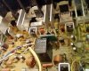
The boards themselves are about as small as they can be, and can hopefully fit in all units. I'm interested to see if that is indeed the case - I'm including a picture of a working pcb in my SA-7700.

I have tested this board thoroughly on my own SA-7700 Amplifier, and have detailed my testing results here. I would love to have some other people verify operation with different models, if they are willing to test out the boards. I have a handful I can mail out to anyone willing to test, and I will update this post and the website when more successful substitutions are confirmed.

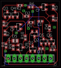
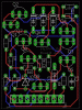
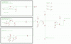
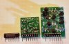
I'm attaching a pic of the boards, the schematic and layouts here. We tried to design the boards to use cheap and common components, and to be easily buildable!

I'm happy to answer any questions any one may have. AK has helped me to restore a couple of amplifiers, and I'm more than happy to contribute to pay it forward!

UPDATE MARCH 2024

@EastPoint has made both the thru hole and SMD boards available via his ebay store! If you need one of these boards, this is the place to get one!

PA3004 Replacement Thru Hole

PA3004 Replacement SMD
 

Attachments
  • all3chips.jpg
    all3chips.jpg
    98.6 KB · Views: 315
  • PA3004v3.0s PCB layout.GIF
    PA3004v3.0s PCB layout.GIF
    104.6 KB · Views: 281
  • PA3004v3.0t PCB layout.GIF
    PA3004v3.0t PCB layout.GIF
    88.9 KB · Views: 275
  • SA7700_internals.jpg
    SA7700_internals.jpg
    135.8 KB · Views: 286
  • schematic.gif
    schematic.gif
    37.3 KB · Views: 353
Last edited:
Register to hide this ad
I appreciate the offer. I would gladly do some testing with quantified results and data when the time is right.

It may also be helpful for those viewing here to understand the range of models using this device.

To my knowledge, some of the included models are:

SX-780
SX-880
SX-980
SX-1080
SX-1280
SX-1980
 
Those plus the SA-7700... I haven't found another SA series unit that uses it, but I certainly haven't reviewed all the schematics!

Looks like these use it as well

SX-790
SX-890
 
Last edited:
Great work.
For those laypeople who are looking to repair their broken Pioneer receiver or amp, perhaps it would be good to state the function of the PA3004: a speaker/output stage protection circuit which includes; DC deviation, B-/+ detection, AC detect, discharge/switching and power muting.
 
Hey guys!

After discovering a failed PA3004 chip on my SA-7700 rebuild, and paying $35 for a single replacement, I asked @merlynski to help me design a PCB substitute, so we can all keep rehabbing these old units without paying exorbitant prices for new "old stock" chips.

Our design goal was to replicate all functions of the original chip, allowing the board to be used as a drop-in replacement in all use cases, in as small a package as possible.

I think we have succeeded admirably, and we're happy to offer the full gerber, design and BOM files here so that any one can use them:

https://guerillavending.com/alex/PA3004/

I think we succeeded in designing a circuit that would replicate all functions of the original chip, and the price is a significant improvement as well - when building 10 at a time, the cost is about $7 a board! I laid out both SMD and thru hole versions, so people that want to build their own can do so, and anyone who needs the tighter size of the SMD version has access to it. The nominal voltages for the PCB in operation are almost exaclt the same as the original chip, so no trouble shooting operations need to be changed.

I intend to generate a assembly quote on JLCPCB.com so that everyone has access to the SMD version even if they can't solder SMD components. In that case, the only solderable component would be the right angle 8-pin connector to the power supply board.

The boards themselves are about as small as they canb be, and can hopefully fit in all units. I'm interested to see if that is indeed the case - I'm including a picture of a working pcb in my SA-7700.

I have tested this board thoroughly on my own SA-7700 Amplifier, and have detailed my testing results here. I would love to have some other people verify operation with different models, if they are willing to test out the boards. I have a handful I can mail out to anyone willing to test, and I will update this post and the website when more successful substitutions are confirmed.

I'm attaching a pic of the boards, the schematic and layouts here. We tried to design the boards to use cheap and common components, and to be easily buildable!

I'm happy to answer any questions any one may have. AK has helped me to restore a couple of amplifiers, and I'm more than happy to contribute to pay it forward!
Outstanding!
 
Great idea! I'll add that description at the beginning of the top post and on the web site!

Great work.
For those laypeople who are looking to repair their broken Pioneer receiver or amp, perhaps it would be good to state the function of the PA3004: a speaker/output stage protection circuit which includes; DC deviation, B-/+ detection, AC detect, discharge/switching and power muting.
 
I created both the thru hole and SMD variant knowing that not everyone has the capability of doing SMD reflow soldering! If you do, the SMD would definitely be my recommendation, especially given the current thru hole component supply shortages! The SMD version uses more common NPN and PNP footprints, so it will hopefully be useful for longer!

Re: selling on ebay, I have no interest doing so, but if someone else does, they are welcome to! Note that the back of the SMD board does say "Please do not sell for profit beyond manufacturing expenses. Material cost = $7". (I suspect that cost would actually come down pretty considerably if more than 10 at a time were made.) - both @merlynski and I wanted to avoid any kind of price gouging with these units, but there is definitely a fair value one could charge for doing the assembly work!

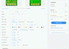
I asked JLCPCB is I could share the quote, and apparently it isn't possible, so here is a screen shot of the ordering configuration I used, with the files that are on the website in post #1 now, for 5 units. The cost is basically ludicrous, but they will charge a $20ish shipping fee as well. I was expecting a bag full of sawdust, but the boards I ordered were of good quality, and came fairly quickly! Of course, you could submit the files to any pcb production house, but any US based one would be at least an order of magnitude (probably two) more expensive!
 

Attachments

  • JLCPCB_v3.0s order.GIF
    JLCPCB_v3.0s order.GIF
    72.6 KB · Views: 129
Last edited:
Alex I have to give ya something. That is awesome! I’m fighting a big issue with my 780 and thinks it’s the 3004. I will take and post pics of the install and how I made out on the thread. Would love to see if this works! I’ll PM you my address. Thanks so much!
Bobby
 
Very interesting and nice work!

This may be helpful, not sure if you have it or if it's been posted.

51010221887_96aa87767e_b.jpg


51010221637_4f5a7a3591_b.jpg
 
Thanks to Alex and the others helping me out IT WORKS in my 780.

What I did notice is because of the location of the relay in the 780 in relation to the 3004 the Lin’s could be longer. I had to put a funky bend in them to get them to seat in the board. I am contemplating using small gauge wire to extend the pins and using some form of insulating mount, perhaps under the main board to make soldering easy. I REALLY had to push to get it to clear. But that was a small price to pay for having my 780 playing the blues again! Thanks again Alex! I will be in touch.
 
Thanks to Alex and the others helping me out IT WORKS in my 780.

What I did notice is because of the location of the relay in the 780 in relation to the 3004 the Lin’s could be longer. I had to put a funky bend in them to get them to seat in the board. I am contemplating using small gauge wire to extend the pins and using some form of insulating mount, perhaps under the main board to make soldering easy. I REALLY had to push to get it to clear. But that was a small price to pay for having my 780 playing the blues again! Thanks again Alex! I will be in touch.

Thanks for the positive report!
Could you post a photo of it as it is installed, from both sides, please?

Since it is originally a Single Inline Package (SIP) it could be installed on the foil side of the board, with the leads coming straight out of the new board instead of bent. then the body of it could be parallel to plane of the main PCB, and it would clear the bottom cover as well.
 
I'm concerned about pin 7 the AC input. It has a definite current draw that affects any voltage divider used with it. The sx-780 for example has a pair of 1 meg resistors set up as a voltage divider. The resultant amplitude of AC at pin 7 strongly suggests that the input impedance of that pin is 10,000 ohms. Changing directly from a PA3004 IC to your substitute is probably going to have excessive AC voltage at that pin. The simple addition of a 10k resistor to ground on the subsititute circuit would seem to be the best cure.

IIAC this should be tested on the chip version first. I discovered this helping someone with their AC detect on the chip.

and, yes I see the diode. but what about negative voltages.
 
Back
Top Bottom