alexhastings
Active Member
I'm concerned about pin 7 the AC input. It has a definite current draw that affects any voltage divider used with it. The sx-780 for example has a pair of 1 meg resistors set up as a voltage divider. The resultant amplitude of AC at pin 7 strongly suggests that the input impedance of that pin is 10,000 ohms. Changing directly from a PA3004 IC to your substitute is probably going to have excessive AC voltage at that pin. The simple addition of a 10k resistor to ground on the subsititute circuit would seem to be the best cure.
IIAC this should be tested on the chip version first. I discovered this helping someone with their AC detect on the chip.
and, yes I see the diode. but what about negative voltages.
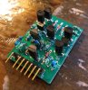
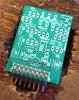
@merlynski and I discussed Pin 7 quite a bit during the design process! The diode and the NPN should clamp the VAC at ~0.7VAC, no? We worried about an insufficient voltage divider in front of it, but were unable to find any examples in existing schematics. Regardless, we should be able to squeeze another 10K resistor in there if we want to replicate that supply current... since it's labeled MAX, might it just be a max leakage current spec for whatever analog to a diode/NPN combo they were able to get onto a chip back in 1982?
I tested the original chip by putting a 24VAC signal (from a wall wart adapter) on a spare 50K pot I had lying around, and adjusted it until I saw it throw a fault on Pin 3 - I consistently saw it throwing the fault when VAC<1.5Vrms
I had actually only seen the block diagram until now - the waveforms and pin functions table would have been helpful, but I was able to figure out most of the info by testing the chip. I still have it sitting here if more testing is needed!
Last edited:

 ) know to use proper handling practices. If it is produced (and assembled) by an outside vendor it will be up to them to package it properly. Our goal was just like yours, produce open source information and let DIY people benefit from it.