• The move to the new server is done. There are some software and database maintenance updates in process. This has us passing the hat around to help out. We appreciate any donations. Seriously, even a dollar helps. The payment page may be found here - https://www.audiokarma.org/support.html

Pioneer SX-1010 Recap & Refresh

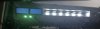
Just waiting on the led bulbs now, I sanded down and sprayed the bottom cover black and the black metal tab that sits underneath the dial face. It was rusty and could be seen behind the glass.

Once I get all that done I will stitch it back up ready for use. Nearly there now, looking forward to it
 
Last edited:
Ok so i have encountered a problem with the LED fitting - I installed bulbs one by one, testing with dbt in between each bulb, so got all speaker select bulbs in, the high, low filter and -20db as well as all source lights, all tested ok, only have the loudness and mono bulb left.
Now for some reason, after securing the board back onto the chassis via the 2 screws, all source, muting and high low filter, mono and loudness LEDs are not working, unit passes DBT and all LEDs i installed did work prior to this, no fuses are blown, checked with meter out of circuit

Not sure what exactly to start with, pin voltages? If so what pins are we looking at?
AWS-068 Pins 1 through 7? Visually everything looks good.

Dammit, was so close to a good run with no major errors afraid to to anything else without your guidance on this, @zebulon1 @merlynski @larryderouin apologies for calling on you all, hope you can help me out here, thanks
lamp.JPG
lamp2.JPG


Very strange, it has to be a dodgy connection, these boards have lots of pins and are pretty tight to access. I will try investigate with unit off and see if i can see anything amiss

Dimmer switch has been cleaned and FM muting switch also

 
Last edited:
I got to the same point and this happened on my
SX-838......

turns out one of the pins broke loose from the solder causing a bad connection on the lamp board. I reflowed and added solder to all the pins on this board. Fixed the problem. I use a chop stick to probe, looking for bad connections.
 
Dimmer switch works as it dims the fuse style lamps.
I am totally lost here, not much at figuring out the schematic, does pin4 of awr-068 feed the dial lights??
Checking wires and poking round does not show anything, all wires connected firmly to each of the pins, all bulbs leads pass pull test, all soldering looks good. wiring itself has no discernible defects, insulation all looks good
So basically all bulbs were verified as working but when i screwed the board back onto the chassis bulbs no longer work.

All fuses on the fuseboard pass for continuity out of circuit

Question - If it was one bulb i soldered incorrectly or not making a good connection the other bulbs should still work?

AWR-068 - Red DMM on pin, Black to chassis. On DBT

1 = 6.2V AC
2 = 0V
3 = 0V
4 = 7V AC
5 = 7V AC
6 = 4.5V DC
7 = 4.5V DC
 
Last edited:
Could the dimmer switch have died? I am totally lost here, not much at figuring out the schematic, does pin4 of awr-068 feed the dial lights??
Checking wires and poking round does not show anything, all wires connected firmly to each of the pins, all bulbs leads pass pull test, all soldering looks good

Question - If it was one bulb i soldered incorrectly or not making a good connection the other bulbs should still work?

AWR-068 - Red DMM on pin, Black to chassis. On DBT

1 = 6.2V AC
2 = 0V
3 = 0V
4 = 7V AC
5 = 7V AC
6 = 4.5V DC
7 = 4.5V DC

I am also new to this, just thought it sounded similar to my experience. I am sure someone who knows more will chime in......

Good luck.
 
Would very much appreciate your help with resolving this issue, im a 30 something year old guy just winging my way along as best, apologies for my dumbness, i need to rely on my fellow aker's to help me fix this - i would be very grateful for all assistance

Continuity checking - Pin 4 in all case below refer to pin 4 on AWS-068. All other pin numbers are located on ASW-068

47 and 4 = Continuity (Beeping) with AM switch ON
46 and 4 = Continuity (Beeping) with FM switch ON
48 and 4 = Continuity (Beeping) with Phono 1 switch ON
1 and 4 = Continuity (Beeping) with Phono 2 switch ON
2 and 4 = Continuity (Beeping) with MIC switch ON
3 and 4 = Continuity (Beeping) with AUX switch ON

I can take any readings needed, its strange no fuses are blown, at a standstill now unfortunately until i can get your feedback

lednoled.JPG
 
Last edited:
Don't get discouraged or say dumbness, we're all learning. You're doing a great job at giving data for others to work with, unlike some other threads with next to no effort in reading the service manual, posting photos/voltages etc. I tried to look at the schematic earlier to help, as well as look at photos on the net. I couldn't find where they lamps were located in the schematic (unlike the tuner dial lamps/stereo etc). I believe they are on one of the selector switch boards.

Any ideas where the lamps in question line up in the schematic or PCB location?
 
Don't get discouraged or say dumbness, we're all learning. You're doing a great job at giving data for others to work with, unlike some other threads with next to no effort in reading the service manual, posting photos/voltages etc. I tried to look at the schematic earlier to help, as well as look at photos on the net. I couldn't find where they lamps were located in the schematic (unlike the tuner dial lamps/stereo etc). I believe they are on one of the selector switch boards.

Any ideas where the lamps in question line up in the schematic or PCB location?

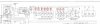
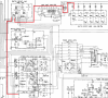
I think this is the location on schematic, i circled in red

bulb locations schematic.jpg

Location of Hi Resolution schematic - Not my work someone else owns this

https://www.flickr.com/photos/27098317@N07/27391164652/
 
Wow, ok I can't read today. Yes there they are. See, we are learning!

Continuity checking - Pin 4 in all case below refer to pin 4 on AWS-068. All other pin numbers are located on ASW-068

47 and 4 = Continuity (Beeping) with AM switch ON
46 and 4 = Continuity (Beeping) with FM switch ON
48 and 4 = Continuity (Beeping) with Phono 1 switch ON
1 and 4 = Continuity (Beeping) with Phono 2 switch ON
2 and 4 = Continuity (Beeping) with MIC switch ON
3 and 4 = Continuity (Beeping) with AUX switch ON

View attachment 1893047


How does pin 45 look on AWS-069? Should be a ground for the lamps. Is it healthy?

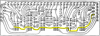
upload_2020-6-9_16-5-17.png

Lets look at AM/pin 47. Pin 47 and ground (chassis) should be reading DCv (around 7 to 8v right for lamps right?). Pin 47 and 45 should be reading DCv when AM is selected. Any luck?
 
Last edited:
How does pin 45 look on AWS-069? Should be a ground for the lamps. Is it healthy? How do i check that, apologies for the silly question. Visually it looks good, no issues that i can see physically. I have continuity between pin 45 and the last point you highlighted on the aux switch

Lets look at AM/pin 47. Pin 47 and ground (chassis) should be reading DCv (around 7 to 8v right for lamps right?) Getting 0v here on DC and AC - AM Selected Pin 47 (red on 47 black to chassis 0vDC) and 45 (red on 47 black to chassis 0vDC-AM Selected) should be reading DCv when AM is selected. Any luck?

I also have continuity between pin 6 on awr-054 and pin 3 on AWS-068
 
Last edited:
Ground wire would be a pin 45 to chassis continuity I believe. Good job looking for AC as well, I should have mentioned that.

The plot thickens, they do not get their voltage from Pin 4 on AWS-068, but pin 2 rather. Guess what, yours is dead. It leads to pin 6 on Power Supply AWR-054. Now what could it be...

AWR-068 - Red DMM on pin, Black to chassis. On DBT

1 = 6.2V AC
2 = 0V
3 = 0V
4 = 7V AC
5 = 7V AC
6 = 4.5V DC
7 = 4.5V DC

upload_2020-6-9_16-57-27.png

upload_2020-6-9_17-5-39.png
 
Hmmm then if i am understanding you correctly, then there is a problem with the power supply????
Issue here is that the board is one of the custom boards so i have no schematic or anything like that to help me out. (even when i have one i am not much use either)

Pin 5 on my power board is putting out 7V AC

Is D7 of AWR-054 a potential culprit? (well its equivalent part on the custom board?
@rcs16 Can i impose on you for assistance please? i know i am hard work, apologies!
 
Last edited:
Hmmm then if i am understanding you correctly, then there is a problem with the power supply????
Issue here is that the board is one of the custom boards so i have no schematic or anything like that to help me out. (even when i have one i am not much use either)

Pin 5 on my power board is putting out 7V AC

Is D7 of AWR-054 a potential culprit? (well its equivalent part on the custom board?
@rcs16 Can i impose on you for assistance please? i know i am hard work, apologies!

Not sure - I'm just following the line down the schematic. You measured pin 5, what does pin 6 show? Any AC or DC? I really am not at the level to understand exactly what is happening there. RCS will knock this out real quick.

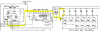
upload_2020-6-9_17-43-40.png
 
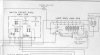
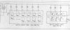
AWS-068 lamp circuit: three of the four switch sections are paralleled together to carry more current

the fourth section is fed by pin 5, and adds two diode drops to the lamp feed to dim them. In bright the diodes are shorted.

There is a "gotcha " here, the fuse CAN test good IN CIRCUIT, yet BE blown. DISCONNECT the fuse from the circuit and THEN check it's ohmage/continuity.
IF you are feeling adventurous, you can set the DMM to measure using it's 10 amp shunt, and substitute the DMM ACROSS the (blown) fuse.
Current will flow through the meter's 10 AMP shunt and spot if there is still an inordinate current draw without zapping another fuse.

Fuse is one of the two 3 amp fuses on the AWR-053 fuse board. Not the awr-054 substitute board.

power comes from xformer violet wire,
goes into pin 4 of awr-063 fuse board
then through F2
comes out of awr-063 fuse board on pin 13
13 then goes into pin 5 of the awr-054 substitute board.
then is turned into DC (somehow) on the awr-054 substitute board.
then comes out of pin 6 of the awr-054 substitute board.
next stop is pin 3 of the AWS-068 dimmer board
through D1 & D2 (the "dimmers") is shorted by the single switch section for bright
and finally out pin 2 of the AWS-068 dimmer board on your highlighted red line.

all this folderol is in case you have to find an inordinate current draw
BUT remember - old fuses can just "die" for no real reason...
 
Last edited:
Hi Mark, I did pull all fuses out of the unit and checked them for continuity, they all passed.
I don't understand the shunt procedure, to be honest with you. Black and red to either side of the fuse holder, meter set to volts? It's a cheapo meter so not sure how good it is. I do have 3.15amp fuses I tried those, no joy
 
Don't shunt, try DMM set to AC to read pin 5 of the awr-054 substitute board. PROBE WITH RED, BLACK PROBE TO BARE METAL CHASSIS GROUND.
set to DC for pin 6 of the awr-054 substitute board.
EXPECT UNDER 10 V SORRY @ CAPS
 
I have 7vac on pin 5 of awr-054.
On pin 6 of same board I have 0v ac or dc

All DMM measurements red on test point black on chassis
 
Last edited:
diode popped on awr-054 substitute board.

Paging Dr. @rcs16....

I wonder if this thread will carry the layout, schematic @ etc for that board?
 
Back
Top Bottom