• The move to the new server is done. There are some software and database maintenance updates in process. This has us passing the hat around to help out. We appreciate any donations. Seriously, even a dollar helps. The payment page may be found here - https://www.audiokarma.org/support.html

Pioneer SX-1010 Recap & Refresh

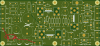
Thanks for the replies, would be lost without you, i am reluctant to touch that board for anything just yet without knowing a bit more more in terms of where D7 is (or its new board version equivalent is). I am not sure if the new board follows the same design of the original so i think in this case Rick may have to throw his eye to the issue. Zebulon may also have a good idea what to look at too.
Hopefully have some diodes in my box, UF4004 / 1N4004 do the trick for the D7 position?

I can safely assume then, that when i screwed the function light board back on to the chassis i shorted one of wires and it popped something on the power board.
 
Last edited:
ACtC-3diDJldWuxUC-SgFAut9QDnYLOcH3OxzVFBEiMS9qH4zHg8nAp48p_DtDjzWKBrDGpFa-NlSesMmDvTLpd8hOlUXQ0Uq8UAbpqGmglGvxdit4mPhiRpu2m7mmys49HxXoFCaqR_l6d9VcpnfRnjnOl8=w1050-h1866-no


Just do a diode check in circuit... tell us how it reads.
 
D7 looks like a 1 amp 1n4004 series, looks like the next step up is a 1n5404 3 amps current, 400 v(?)

original on awr-054 is 1s1885 1amp, 100v so even I would probably would have used a 1n4004....


upload_2020-6-10_5-3-17.png

Wise move to wait for Rick, you won't hurt anything to probe the diode leads, and it might not be the diode, like a trace surrendered or a cap shorted.
 
Last edited:
OK so can I do the diode check with the diode in circuit, or do I lift one leg and test?

If the diode tests bad, I should pull each component marked on your drawings in red and also test?

I should also test continuity between each of the pads in the marked up drawings?

Let me know if that sounds OK, or not, thanks
I will wait on Rick before I do anything other than the diode check
 
Well i am pretty embarrassed, was thinking of just telling porkies by saying that i tested D7 and it was shorted, but no, D7 basically turned into D3.5 and D3.5.
The thing was in half folks,seriously, and i did not spot it! :(
Anyway i know how dumb that is but it will be the last time an exploded diode gets past me :)
Well i bloody hope so anyway! Man i feel stupid
 
Last edited:
All lights are now installed and working as they should thanks everyone for the help.
Dial pointer bulb is a delicate operation, very easy to break the pointer and mash up the housing too
I cannot recommend Dave highly enough for his bulbs they really are great, there is a reason he is the go to guy for these.

D7 replaced and caps tested good in my cheap tester, the new power board is actually difficult to solder on even with plenty of flux .
All traces marked up had continuity and look fine with no discernible issues.

Only thing left to do in the unit is the relay, i do have one but i do not have the standoffs to allow for fitment, unless i reuse the originals cover.

I am thinking of leaving the current relay installed as it is working ok, so might push that job out for another bit.

the dial pointer movement feels a little stiff, how do you guys normally smooth this out, i have already cleaned the groove metal so that it is sliding on a clean surface, but do you guys lubricate the channel with anything? Silicon grease?
 
Last edited:
Definitely replace the relay--it's very much worth it. Send me a PM and I can mail you the standoffs free of charge, assuming you're in the USA.
 
Definitely replace the relay--it's very much worth it. Send me a PM and I can mail you the standoffs free of charge, assuming you're in the USA.
Thank you for your kind offer, it is very much appreciated.
I did some searching around and i found some standoffs from an old pc, so i think i can make it work. It might not be as pretty but certainly looks like i can get it functional and still ensure relay pins are "underneath" the chassis. You are right, i have done everything to this unit so relay will get changed today.

After that it is time to dial it in for one final time and seal it up.
Then it is time to start listening to it, instead of looking at it

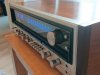
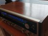
I polished up the cover and dial face a bit, so hopefully it will be looking as good as it sounds
 
Last edited:
What list are you using for this rebuild? In some aspect the full UPW and UKL is half correct. If its not too much trouble you may want to toss a few of those UPWs back in there. However it will probably be fine as is. Here is some info:

If you want to use film caps:
- 0.1uf to less than 1.0 uf: Wima MKP2
- 1uf to 4.7uf: Wima MKS 2
cea >> Nichicon UPW
ceanl, cssa, csza >> nichicon UKL if film not possible - (low noise, low electronic leakage)

For example, here is a snip of the service manual for this board. As you know ignore the mylars and such, just focus on the electrolytic and blue tant caps. Notice the first few letters of the part numbers? They compare to the list above. There are of course other choices for which type of caps to use but at least it gives you an idea on if you should use a UPW type cap or UKL type cap.

View attachment 1880821
Just curious about the film cap designations. Reading the data sheets for the Wima MKS2 and MKP2 capacitors, it looks like the MKS2 is “for general DC applications” and the MKP2 is “for high frequency applications.” Could I just use MKS2 caps everywhere that’s not high frequency? The MKS2 is available in capacitances from 0.01uF to 10uF, but I imagine the size of these caps above 4.7uF would be the limiting factor on most boards. Is there a specific reason to use MKP2 caps for the 0.1uF to 1uF range? I’m not trying to discredit you, I am just curious and want to learn more. Thank you for this post. It was super helpful information. I referenced it when I ordered parts to recap the tuner in my SX-1250.
 
Just curious about the film cap designations. Reading the data sheets for the Wima MKS2 and MKP2 capacitors, it looks like the MKS2 is “for general DC applications” and the MKP2 is “for high frequency applications.” Could I just use MKS2 caps everywhere that’s not high frequency? The MKS2 is available in capacitances from 0.01uF to 10uF, but I imagine the size of these caps above 4.7uF would be the limiting factor on most boards. Is there a specific reason to use MKP2 caps for the 0.1uF to 1uF range? I’m not trying to discredit you, I am just curious and want to learn more. Thank you for this post. It was super helpful information. I referenced it when I ordered parts to recap the tuner in my SX-1250.


I'm not an expert, however the difference is the MKS are pretty small at 4.7uf and below. They are made out of Polyester. The MKP are polypropylene and are more desirable. They have a much larger size than the MKS caps but below 1uf (I think it's actually 0.33uf and below) their sizes are similar to the MKS line.
 
I'm not an expert, however the difference is the MKS are pretty small at 4.7uf and below. They are made out of Polyester. The MKP are polypropylene and are more desirable. They have a much larger size than the MKS caps but below 1uf (I think it's actually 0.33uf and below) their sizes are similar to the MKS line.
Thank you. That makes a lot of sense. I just decided to start using these caps with my tuner board, so I’m just now getting familiar with them. Now I wish I’d known to use them everywhere else possible in my 1250!
 
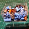
Here is what was left, keeping the original relay and any of the transistors that are not on the naughty list. Doesn't really look like much
DSC_0390.JPG
 
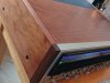
For the cover I used fiddes and sons supreme wax - stripped pine, I really like how it turned out shined the cover up really well and gave it much more life, I'll try take a few pictures tomorrow.
 
Great work! Glad to read a success story after all your work/troubleshooting. I think your ability to ask questions and execute will really be rewarding in this hobby. How does it sound? Let's get some photos :)
 
Thanks for the kind words!!
I would have been happier to get through it without any issues, but thankfully we got there in the end.
It sounds great, I'm not great with the vocabulary for describing sound but it's sounds, full and warm through a nice pair of castle conway mk2 speakers.
There is a reason the 1010's have the following they do.
I'll grab some pictures tomorrow.

I did try and make a thread that could potentially serve as some help to anyone recapping one of these. I'd like to think someone will be viewing this thread, along with all the other threads, in prep for doing their own recap in a year from now.
 
There IS a new AK'er with a SX-939 that needs to be upgraded, and most of the 1010 parts are applicable to 939's.
 
You did VERY GOOD, Paul. Don't ask MARK how many near Heart Attacks I gave him when I did mine back in 2009 (It was my 1st Solid State rebuild, and I had just done a Radio Craftsman 550 amp, and RC10 tuner) and I thought I was hot ****. NOT! But with his gentle tutalage (usually a virtual 2x4 upside the head twice weekly,:D:D) I muddled thru. I took it down to a HAM operator who had the gear, and we did the FTC pretest, which IIRC was (1hour on 200W 8Ω dummy loads, running 33% of power output). It then tested out considerably better than as new. IIRC about 125wpc per channel, 20-20000Hz, into 8Ω, with THD lower than spec. I can't remember how low it was now. I ended up selling it a couple years later to fund a re-union trip. But i have a SX-939 to replace it in the greater scheme of things. Closest thing to a 1010.
 
Back
Top Bottom