• The move to the new server is done. There are some software and database maintenance updates in process. This has us passing the hat around to help out. We appreciate any donations. Seriously, even a dollar helps. The payment page may be found here - https://www.audiokarma.org/support.html

Repair Pioneer A9 NSA

Part of your answer sits on the title (first) page of the service manual. Different models, different transformer (primary windings).

That schematic does not fully represent the power line input power transformer windings that you have..
different models, different transformers.

View attachment 2827521

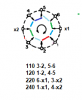
It shows a dual voltage winding 220 / 240v transformer. ATT-762. For models HE and HB.

Here is a 4 voltage transformer used on the SX-1980, hopefully the wire color scheme for the primary windings is the same.

NOTE: it has a 120v & 10v winding, and a 120v & 110v winding. That's NOT a typo!! I DID say TEN volts.

View attachment 2827507

Mark you are a genius! Thank you again! That was right on target!

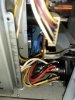
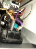
The problem is right here in the connection of these cables. It is possible that the amplifier is connected to the wrong voltage or there is some defect. Let me clarify the situation.
The colors do not match the SX-1980 exactly.
That's why I compare the suspicious amp #1 with another A9 - amp #2 ,that I have and the transformer of this two amplifiers are identical.
The #.2, amp has wires for four different voltages - 110V, 120V, 220V, 240V. And there are 7 wires at the input (Violet, Gray, Red, Brown, Black, Yellow, White).

Amplifier #1 is the same transformer as amplifier #2-
But it does not have the corresponding voltage selector for these wires.
Its voltage selector is for two voltages...220V and 240V!

The voltage selector was replaced with the wrong one because it says on the back panel that the amplifier is for four different voltages.
I immediately start checking the correct amplifier #2 in what position and what wires are connected for 120V, in order to compare them with those of the problematic amplifier #1.
The wires that enter the transformer of amp #2 when the voltage selector is in the 120 volt position. are 4 – Gray combined with Brown and Violet combined with Black.

The wires that go into the transformer of amp #1 are all 3 because they are all 7 and 4 are not connected, And these are: White, Violet and Brown, as Brown or White can be combined with Violet.

This is a real mes . I even think that in one position it is simply a short circuit.
I have to check through the DBT because such small coil resistances probably won't be able to be measured accurately with this voltmeter.
In this situation, I have to look for such a voltage selector (the original one also has a fuse in it).

The other option is to connect the wires in the position that the original amplifier is connected for 120 volts and see if they short, if there is no burned coil and what voltage they give. And did the amp will work in this situation.

I have no idea where such a voltage selector can be found.

I looked at the schematic of this SX-1980. I even downloaded the wiring diagram from Hi-Fi Engine just out of interest.
" That's NOT a typo!! I DID say TEN volts."
What can give this amp 10 volts at high amperage? Does this connect to a welder?
It also struck me that they test it at half its power. Is this because they didn't have the proper instruments to measure it's full power characteristics?
Corrected- Yellow changed with a Violet in amp #2
Sorry for the mistake.
 
Last edited:
What can give this amp 10 volts at high amperage? Does this connect to a welder?
I hope that was a joke.

Test at half power? no way...
FTC calls for BOTH channels driven in amplifier power tests, at least until the low information braggarts started inflating the numbers.
Then it's caveat emptor. as in "let the buyer beware"

I see no problem. Also remember phasing. Constructive and destructive in the core...

upload_2023-3-15_22-21-30.png


stated another way:

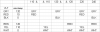
110v and 120v have two windings in parallel, 220 and 240 have the same windings in series.

110 hot to GRY, RED to neutral, also second winding in parallel on the 110 v power line 110 hot to YEL, WHT to neutral

120 hot to GRY, BLK to neutral, also second winding in parallel on the 120 v power line 120 hot to BRN, WHT to neutral

220 hot to GRY, RED to YEL (floating), WHT to neutral

240 hot to GRY, BLK to BRN (floating), WHT to neutral
 
Last edited:
I hope that was a joke.

Test at half power? no way...
FTC calls for BOTH channels driven in amplifier power tests, at least until the low information braggarts started inflating the numbers.
Then it's caveat emptor. as in "let the buyer beware"

I see no problem. Also remember phasing. Constructive and destructive in the core...

View attachment 2828698


stated another way:

110v and 120v have two windings in parallel, 220 and 240 have the same windings in series.

110 hot to GRY, RED to neutral, also second winding in parallel on the 110 v power line 110 hot to YEL, WHT to neutral

120 hot to GRY, BLK to neutral, also second winding in parallel on the 120 v power line 120 hot to BRN, WHT to neutral

220 hot to GRY, RED to YEL (floating), WHT to neutral

240 hot to GRY, BLK to BRN (floating), WHT to neutral

"I hope that was a joke."
Of course it's a joke. I love such powerful monsters. I didn't know this one was so powerful. And regarding the testing, I was simply surprised, here is the fact that they gave data for 135W and it is 270W
20230316_011736.jpg

I would love to have it and hear it play, but it's too expensive and I can't afford it. I don't even think I can find a damaged one at an affordable price. In its parts I saw a strange transistor- CBEC .. are these two collectors or a complementary pair in one case? And really - what is this 10 Volt input for? For some kind of diagnostics?


Regarding A9 - I made a correction in the previous post - I had mistaken Violet with Yellow for the wires entering the 120V transformer. Sorry! Will this affect the table?
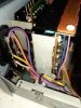
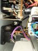
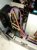
Yes, there is no problem with the connection, but there is a problem that I do not have the correct voltage selector and the one that is installed from some other device, apparently only for Europe, there is simply no place to connect all the wires and there will still be unconnected wires.So I have this:20230315_174125.jpg

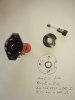
But this is wrong switch from something else. And I need this:

20230307_200035.jpg


But let see first how will work connected on 120V with a wright wires.
 
"I hope that was a joke."
Of course it's a joke. I love such powerful monsters. I didn't know this one was so powerful. And regarding the testing, I was simply surprised, here is the fact that they gave data for 135W and it is 270W
View attachment 2829064

I would love to have it and hear it play, but it's too expensive and I can't afford it. I don't even think I can find a damaged one at an affordable price. In its parts I saw a strange transistor- CBEC .. are these two collectors or a complementary pair in one case? And really - what is this 10 Volt input for? For some kind of diagnostics?


Regarding A9 - I made a correction in the previous post - I had mistaken Violet with Yellow for the wires entering the 120V transformer. Sorry! Will this affect the table?
Yes, there is no problem with the connection, but there is a problem that I do not have the correct voltage selector and the one that is installed from some other device, apparently only for Europe, there is simply no place to connect all the wires and there will still be unconnected wires.So I have this:View attachment 2829069

But this is wrong switch from something else. And I need this:

View attachment 2829082


But let see first how will work connected on 120V with a wright wires.

Finally I found a voltage selector switch on eBay that looks the same. Let's see. If so it would be easier for me to copy and solder the wiring as it is on the working amp. I'm waiting for it to be delivered.
 
CEBC transistor just has two collector connections. Nothing else special (well - discounting the die geometry).

Having done several successful SX-1980 power amplifier output transistor resurrections with mjl4302, mjl4281 (sx-1280's as well), I am positive that that (edit: the cebc explanation) is correct.

You have hopefully realized that on 110 and 120 volts both primaries are energized in parallel.
and that for running them at 110 volts, power goes into one at "120" and comes out at "10". while the other primary goes in at "110" and comes out at "0".
 
Last edited:
CEBC transistor just has two collector connections. Nothing else special (well - discounting the die geometry).

Having done several successful SX-1980 power amplifier output transistor resurrections with mjl4302, mjl4281 (sx-1280's as well), I am positive that that is correct.

You have hopefully realized that on 110 and 120 volts both primaries are energized in parallel.
and that for running them at 110 volts, power goes into one at "120" and comes out at "10". while the other primary goes in at "110" and comes out at "0".


"...mjl4302, mjl4281 (sx-1280's as well)"
Don't these transistors also work for A9?
The two hundred watts mjl we put in A9 are super strong. They withstood all kinds of short circuits, as well as the stupid dog test that I applied to them with the volume potentiometer fully open. Not only did they withstand, but none of them changed their gain coefficient hFE and completely preserved their nice musical sound. I can't say the same about the original RETs, of which I already have about 12 burned out and the remaining 12 are with gain far below the minimum according to the specification. As I have only burned 8 of them in two overloads from positive feedback .
I may be repeating myself, but I think the old RETs may have been better in something written in their specifications 43 years ago, but nowadays they have weakened gain and burn out very easily.

I'm already on the trail of the SX-1980. It cannot start. There is a pot of flowers on it and they didn't throw it away because it's heavy and they don't have an elevator. I'm worried about the transport from Europe to here. All my A9s were warped by the mails and I have straightened them from the dents. If the front panel -1980 is bent , on this amp it will be irreparable.

About A9
I'm still struggling to understand the instruction in #415 and #416. I understand the wiring in the chart theoretically, but I don't understand exactly which cable should go where on the voltage selector because it has two shorted bridges and one of them is through a fuse. Also about the Violet cable - "microtemp" - is that a thermal overload cut out inside the transformer?
What I was able to trace from the wires of the original A9 amplifier for the 120 volt position is:

Gray and Brown are shorted and the power supply is between Black and Violet, with the Black having a fuse.

Here I see this "120 hot to GRY, BLK to neutral, also second winding in parallel on the 120 v power line 120 hot to BRN, WHT to neutral", which seems different to me. I have checked several times to make sure there is no error, but this is what comes out.It is possible SX-1980 and A9 to have some difference into the PS wiring?
 
"...mjl4302, mjl4281 (sx-1280's as well)"
Don't these transistors also work for A9?
The two hundred watts mjl we put in A9 are super strong. They withstood all kinds of short circuits, as well as the stupid dog test that I applied to them with the volume potentiometer fully open. Not only did they withstand, but none of them changed their gain coefficient hFE and completely preserved their nice musical sound. I can't say the same about the original RETs, of which I already have about 12 burned out and the remaining 12 are with gain far below the minimum according to the specification. As I have only burned 8 of them in two overloads from positive feedback .
I may be repeating myself, but I think the old RETs may have been better in something written in their specifications 43 years ago, but nowadays they have weakened gain and burn out very easily.

I'm already on the trail of the SX-1980. It cannot start. There is a pot of flowers on it and they didn't throw it away because it's heavy and they don't have an elevator. I'm worried about the transport from Europe to here. All my A9s were warped by the mails and I have straightened them from the dents. If the front panel -1980 is bent , on this amp it will be irreparable.
.

About A9
I'm still struggling to understand the instruction in #415 and #416. I understand the wiring in the chart theoretically, but I don't understand exactly which cable should go where on the voltage selector because it has two shorted bridges and one of them is through a fuse. Also about the Violet cable - "microtemp" - is that a thermal overload cut out inside the transformer?
What I was able to trace from the wires of the original A9 amplifier for the 120 volt position is:

Gray and Brown are shorted and the power supply is between Black and Violet, with the Black having a fuse.

Here I see this "120 hot to GRY, BLK to neutral, also second winding in parallel on the 120 v power line 120 hot to BRN, WHT to neutral", which seems different to me. I have checked several times to make sure there is no error, but this is what comes out.It is possible SX-1980 and A9 to have some difference into the PS wiring?

The voltage selector was supplied. It wasn't listed as being for the A9 so I didn't find it right away. Good thing that was a nice photo to recognize it. This is "Pioneer SX-1050 SX-950 SX-850 SX-3700 SA-8800 Voltage Selector & Fuse Holder" which is the same for Pioneer A9, for 4 types of voltages.
Corrected: Added more pictures of this switch:
20230320_202640.jpg
20230321_121423.jpg 20230321_120957.jpg
20230321_121417.jpg 20230321_121423.jpg 20230321_122703.jpg 20230321_122713.jpg 20230321_124051.jpg 20230321_124415.jpg

There is a little difference between the original A9 wiring and the other models with the same switch
 
Last edited:
looks like there are remnants of wire colors clinging to the pins. invaluable

A clear photo of the bottom would be appreciated.

Then with an indication of which pins have conductivity together, we will have a fighting chance of solving the wiring.
 
looks like there are remnants of wire colors clinging to the pins. invaluable

A clear photo of the bottom would be appreciated.

Then with an indication of which pins have conductivity together, we will have a fighting chance of solving the wiring.

I made corrections on my previous post regarding the new selector switch (used from another amps)

Here I will post more pics about the wiring .

Because there is no information on the internet about this particular part of the 4 voltage diagram for A9.

I also opened the original unrepaired amplifier where the wires are still with coiled montage and not soldered. I took pictures. And also a drawing . The drawing is a bit noobish, but it's the best I can do. I have simply indicated which pin has what color cable and where what is visible goes. I have no idea what is in the transformer, nor what windings. If I need to give any more information let me know. My intentions are to use the amplifiers on 120V , 220V and 240V.

I also indicated the combination of the shorted wires for the varios voltages. I did this by tracking the position of the cap with the shorted pins to which position go to the different voltages. Let me know if something is looking wrong to not start to copy and solder the wires.
20230321_121405.jpg
20230321_122713.jpg
20230321_124101.jpg 20230321_131718.jpg 20230321_131733.jpg 20230321_131743.jpg 20230321_131758.jpg 20230321_201023.jpg
I wish from this to be possible to be drawn the electrical diagram, to be able to check the resistance of the windings for short or burn out in case like this with a questionable repairing of the voltage selector.
Already I desolder the wrong installed selector from #1 amp and start checking the resistance of 110 V according my drawing-but I think that something is wrong. Did I do real something wrong after chek this a lots of times? All the wires looks to be according to the drawing.
 
Last edited:
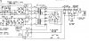
Not sure if this is of any value but here is part of the schematic for the A-8 (S,S/G - General export/US military model) showing the transformer and line voltage selector switch wiring. Perhaps there are some similarities with the A-9.

A-8 Model S,SG Power.jpg
 
Thanks LesE, A8 had slipped my mind.

upload_2023-3-22_1-43-29.png

upload_2023-3-22_1-44-9.png

As you can see, while there are 8 terminals on the back of the unit,
only six were named with a number.
What would be next from three to be four was SKIPPED (your 5 is really 4)
did the same for what you call 8, which is really undefined like the "fourth" pin.
I think when you readjust your drawing to these quirks of the component's pin identification, things will become clearer to you.

It may be that the ebay component is wrong for it, I am digging into that. (struggling with the images...)
 
Last edited:
Not sure if this is of any value but here is part of the schematic for the A-8 (S,S/G - General export/US military model) showing the transformer and line voltage selector switch wiring. Perhaps there are some similarities with the A-9.

View attachment 2835290
Thank you ,LesE!
The windings and the colors looks the same!.
The selector wiring may be is a little different , not sure will see tomorrow.
Let me post the measured resistances between the wires going to the transformer and to see Mark's conclusion.
But at list we got the decryption of the windings into the transformer!
 
FYI ... the AKX-063 voltage selector switch was frequently used during the early 1980's. Here is a list of the models that used this part (there are likely others as well).

AKX-063.jpg
 
FYI ... the AKX-063 voltage selector switch was frequently used during the early 1980's. Here is a list of the models that used this part (there are likely others as well).

View attachment 2835361

So in this chart AKX-063 is not applicable for A9.

But if this is AKX- 063 (https://www.ebay.com/itm/141728620360 ) This is not likes this witch I have and listed above.

Also in the service manual #35 selector switch is AKX-057 for Europe for only two voltages-220V and 240V.

The switch I bought is different than those two switches .


And as I wrote in the previous two posts, this is the exact selector that is installed on two of my amplifiers, and one amplifier is in absolutely original condition without any intervention in it for repairs. I have also written for which amplifiers it is compatible as it is listed on ebay.

This part of the schematics is the most modified and there is the least information about the modifications. And that's why it's hard to find information.Also two different types of regulator boards I see for the voltage modification , coming with the different selectors- with a fuse and without fuse

Anyway, I measured the resistances of the wires coming out of the transformer. I think they match the windings on the drawing you sent..But from the diagram became clear what the coils were .
The selector is different on the diagram. I don't have such a selector .
I paid over $30 for this one and have nothing to do with it.
20230322_115548.jpg 20230322_115554.jpg 20230322_115626.jpg So I installed it the same way it is installed in the other 2 amps and it worked.. I just resoldered one leg of the capacitor. I haven't tested it yet to see if the power has increased and also if it works at the higher voltages, but I'm about to do that as well. But I need a fuses to do this. Lets see what will happen.
 
I don't have all models covered in the database due to a lack of availability of certain manuals but as it turns out, I just discovered that I do have the additional service manual that covers the A-9 S,S/G models and the correct part number is AKR-031 which was used in many models including the SX-1980. Here is the pertinent part of the schematic for the A-9 S,S/G model:

upload_2023-3-22_15-43-35.png

I'm not sure how I missed this one but I will be updating the database to reflect the A-9 S,S/G model data. Here is the list for the AKR-031 including the A-9 S,S/G:

upload_2023-3-22_15-52-25.png
 
I don't have all models covered in the database due to a lack of availability of certain manuals but as it turns out, I just discovered that I do have the additional service manual that covers the A-9 S,S/G models and the correct part number is AKR-031 which was used in many models including the SX-1980. Here is the pertinent part of the schematic for the A-9 S,S/G model:

View attachment 2835759

I'm not sure how I missed this one but I will be updating the database to reflect the A-9 S,S/G model data. Here is the list for the AKR-031 including the A-9 S,S/G:

View attachment 2835768

YES! You got it!
This is the diagram!
And the switch AKR-031 is this:( https://www.ebay.com/itm/144994778077?hash=item21c25cbbdd:g:R-EAAOSwIs9hYMBs&amdata=enc:AQAHAAAA8CS5wJqJf+bMfpIBu715Oosogb9/X0DxNNiy9Xd3LhK9DOPFNZdeoPDpBZZrXBhznkGNRLW9K1vu7imMWqLJKvxNCMKuZuAi7T7h8NG5v2hChPdx8r/CAHMqzNersd6f3tRb5UXchYSNC1bDHnf65EaFs7Bh9IHdUHmGEDZZpSKrgEZHnBguBNvXsiBQWNo6Wbzl1o6KqqWhRfccwUcQ0ROnlM7GeGxvQFso3yTrglyMBWspIh004bW4PLAKfVzAj260yAEmubfZIWqkRXttcpLCFBhx5/PuTZqZli7zSdj6YT7wkHP/S9m+zVAE0gSQhQ==|tkp:Bk9SR6i-qsfhYQ) -

And I listed many pics above in #423 on this switch.
This is the selector switch I bought and install already.

The good think is that it works and bring the amp to the normal power.
I will post the pics of the measurements.
Thank you LesE!


The good news, as I wrote above, is that the reduced power issue has been successfully repaired and amplifier #1 now meets the power specification in the service manual.

Thank you Mark! Thank you LesE!

Here I post pictures of the measurements. The left voltmeter is connected to the large capacitors of the unregulated voltage –t to + which without load is about |114| V. The right voltmeter is connected to a load of 100 watts 8 ohms in water for cooling. A photo of the same test rig is posted in previous posts.

One picture is at 100 watts of power at 20 Hz - the supply voltage is 100V - exactly the same as the other amplifiers at such a load20230322_214322.jpg ….

Next is sine clipping power at 1000Hz - 31.71V at 8 ohms (125W) where the power supply holds 99.9V, which is the same as with the other 3 amplifiers….

20230322_213807.jpg
And finally, a stupid dog test at 1000 Hz with the volume turned all the way up. I do it if there is something will burn , to burn until I have not fully assembled them with the front panels.
It turns out that it also withstands: 41.4V (214 Watts) at a supply voltage of 96 volts. – same as the other 3 amps.Also very big improvement in sound.
I will also do tests at 240 volts to compare if there really is a difference, because I read somewhere that at 240 volts these amplifiers play better. But I need to see where to order fuses that change in the voltage selector when the voltage is changed. These are 6.5X30mm glass fuses 110V 10A and 240V 5A.
 
Last edited:
Before ending this thread, I have decided to do some additional measurements and experiments with the A9, which will certainly raise questions for the experts. During the time when I did not write here, I was busy repairing an oscilloscope, which was given to me as a gift. Of course was in not working condition.
. HP54510B with non-working power supply and memory loss.
I replaced the LM350 in the power supply and 8 capacitors that really had a leak and soldered a 3 volt battery for the memory. And now it works.

Of course I only desoldered and soldered and my friend from Europe told me what to do.

I also have a simple wave generator. Also, if anyone has a suggestion as to what exactly is interesting to measure on these refurbished amplifiers and compare it with an original A9 in excellent condition - please write here.
 
Last edited:
One of the amplifiers (#2) shows this kind of distortion when tested with rectangular pulses (around the 20th gain).…


When testing with a sine signal, there is almost no distortion... here it is around 1 kHz ... 101 kHz ... 274 kHz ... and 1.1 MHz, where there is already visible distortion.

It's also very "musical" and plays very well, but I'm concerned that this type of distortion could cause self-excitation to burn out the final stage again. Here I am waiting for an opinion and for Mark to have his say.

For information - the other three A9s have the same frequency band and at very low gain, which is also the limit of saturation, they reach a little over !.1 MHz sine signal, but around 1000 Hz rectangular pulses reproduce them much better.

Another important piece of information is that I removed the GWH-146 amplifier board and the OPS and swapped them with the other A9 amplifiers, and vice versa.

The result is the following” - this amplifier #2 always preserves the distortions with every amplifier board and OPS, and only with the rectangular pulses in exactly the same way. And each of the other two amplifiers that did not have distortions with rectangular impulses also did not have distortions with the amplifier board and OPS from amplifier #2, which was distorting with them. This means that the reason is not in the OPS and also in the amplifier board GWH-146. But where could it be then? And the same for both channels...? The big capacitors? Or those on the potentiometer board?

(Sorry I was not able to place the pics into appropriate place into the text to be more clear everything)

20150103_092830.jpg20150103_093153.jpg20150103_093528.jpg20150103_093718.jpg20150103_093939.jpg20150103_080924.jpg
 
Last edited:
I would surmise that only one channel of two in the #2 GWH-146 board is exhibiting these symptoms.

Your concerns are valid. This indeed could have brought down that amp.

These kind of things are usually caused by an out of value anti-oscillation capacitor. Sub one microfarad.

an inventory of that board reveals:

Left Channel (from schematic)

C1 150p 500V
C3 68p *** NOTE *** on some schematics a typo of 58p exists.
C7 82p
C9 0.0033
C15 15p
C17 0.0047
C19 47p
C21 47p
C25 0.033 400V
C43 15p


Right Channel

C2 150p 500V
C4 68p
C8 82p
C10 0.0033 400v
C16 15p
C18 0.0047
C20 47p 500v
C22 47p 500v
C26 0.033 400V
C44 15p

( from Parts List in Service Manual:)
ACF-015 C1,C2 Mica (150p/500v)
ACF-017 C19,C20, C21, C22 Mica (47p/500v)
CCDSL 680J 50 C3,C4 68pF 50v
CCDSL 820J 50 C7,C8 82pF 50v
CCDSL 150J 50 C15,C16,C43,C44 15pF 50v

CQMA 472J 50 C17,C18 0.0047uF 50v
CQMA 332K 400 C9,C10 0.0033uF 400v
CQMA 333K 400 C25,C26 0.033uF 400v

(from Tuning Fork Publications: )
CCD ceramic capacitor disc
SL ordinary cap where no thermal coefficient is rated

CQM a mylar capacitor polyester film

One of these ten capacitors on that channel is out of tolerance, probably drastically low.

removal and testing of component value is about the only reliable way to find it. well, swapping channel to channel too.

1687377026869.png
 
Last edited:
Back
Top Bottom