• The move to the new server is done. There are some software and database maintenance updates in process. This has us passing the hat around to help out. We appreciate any donations. Seriously, even a dollar helps. The payment page may be found here - https://www.audiokarma.org/support.html

Repair Pioneer A9 NSA

I would surmise that only one channel of two in the #2 GWH-146 board is exhibiting these symptoms.

Your concerns are valid. This indeed could have brought down that amp.

These kind of things are usually caused by an out of value anti-oscillation capacitor. Sub one microfarad.

an inventory of that board reveals:

Left Channel

C1 150p 500V
C3 68p *** NOTE *** on some schematics a typo of 58p exists.
C7 82p
C9 0.0033
C15 15p
C17 0.0047
C19 47p
C21 47p
C25 0.033 400V
C43 15p


Right Channel

C2 150p 500V
C4 68p
C8 82p
C10 0.0033 400v
C16 15p
C18 0.0047
C20 47p 500v
C22 47p 500v
C26 0.033 400V
C44 15p

ACF-015 C1,C2 Mica (150p/500v)
ACF-017 C19,C20, C21, C22 Mica (47p/500v)
CCDSL 680J 50 C3,C4 68pF 50v
CCDSL 820J 50 C7,C8 82pF 50v
CCDSL 150J 50 C15,C16,C43,C44 15pF 50v

CQMA 472J 50 C17,C18 0.0047uF 50v
CQMA 332K 400 C9,C10 0.0033uF 400v
CQMA 333K 400 C25,C26 0.033uF 400v

CCD ceramic capacitor disc
SL ordinary cap where no thermal coefficient is rated

CQM a mylar capacitor polyester film

One of these ten capacitors on that channel is out of tolerance, probably drastically low.

removal and testing of component value is about the only reliable way to find it. well, swapping channel to channel too.

View attachment 2915110
Thank you for your quick and accurate reply Mark!
I will proceed this instruction and will list the result.
 
CAPACITORS  DISTORTION.jpg
I checked all these capacitors with de soldering measurement and soldering.
They turned out to be in order and have not changed their values.

Also, as I wrote above in #433 this GWH-146 also was tested on another amplifier and there it worked normally.

So the question remains : is it possible these distortions, with identical configuration for L and R channel, to be from somewhere other than GWH-146 and OPS ?
Also can we trace them by the signal to find from where they coming?
 
I checked all these capacitors with de soldering measurement and soldering.
They turned out to be in order and have not changed their values.

Also, as I wrote above in #433 this GWH-146 also was tested on another amplifier and there it worked normally.

So the question remains : is it possible these distortions, with identical configuration for L and R channel, to be from somewhere other than GWH-146 and OPS ?
Also can we trace them by the signal to find from where they coming?
Well, this is embarrassing, it is the exact opposite of what I had been contemplating. I'm not sure how exactly I committed this error.

So it is just on one chassis, and is on both channels of that chassis.

how is the square signal input?

I will assume AUX in and "Line Straight"

If so, there are no gain (amplifier) circuits between the aux receptacle and the GWH-146 pins 1-1 & 1-3 amplifier inputs.

also:
here it is around 1 kHz ... 101 kHz ... 274 kHz ... and 1.1 MHz, where there is already visible distortion.
what did you mean, and do, that involves 101khz, 274khz and 1.1MHz ?

The feedback is immediately suspect. The "main" feedback point is the common point of all the emitter resistors of the output transistors.
It is to be noted that the feedback is taken before the series inductor on the amplifier output.
The feedback has to come back to the amplifier card, and what is in between is important.

Is there a significant change in the wires that carry this signal back to the GWH-146 from GWX-593 & GWX-594 on just this chassis?


Remember that ALL the speaker current flows through that wire as well,
since it must transit the series inductor zobel filter before being sent to the speakers.
 
Well, this is embarrassing, it is the exact opposite of what I had been contemplating. I'm not sure how exactly I committed this error.

So it is just on one chassis, and is on both channels of that chassis.

how is the square signal input?

I will assume AUX in and "Line Straight"

If so, there are no gain (amplifier) circuits between the aux receptacle and the GWH-146 pins 1-1 & 1-3 amplifier inputs.

also:

what did you mean, and do, that involves 101khz, 274khz and 1.1MHz ?

The feedback is immediately suspect. The "main" feedback point is the common point of all the emitter resistors of the output transistors.
It is to be noted that the feedback is taken before the series inductor on the amplifier output.
The feedback has to come back to the amplifier card, and what is in between is important.

Is there a significant change in the wires that carry this signal back to the GWH-146 from GWX-593 & GWX-594 on just this chassis?


Remember that ALL the speaker current flows through that wire as well,
since it must transit the series inductor zobel filter before being sent to the speakers.
So.
Explanation

The description of all the actions I perform with these 4 amplifiers plus one spare amplifier board, plus one spare set of original OPS set is really difficult and can lead to confusion.

Essentially:

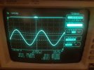
1. I suggest that we simplify things by ignoring the pictures with the sine frequencies and looking only at the rectangular pulses - I will explain more about them and post more of them later.

2 . To look at each board of the amplifier like a black box until we determine in which black box the defect is - this is my method because it is not clear to me what happens inside the boards and how exactly they work.

I'll try to explain more clearly what I did.

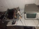
-The rectangular pulses from the generator are also rectangular at 5 us./div on the oscilloscope.-by testing the generator only

- From the generator, the cables are plugged into the AUX input of the amplifier, which is located on the AWF-052 (maybe there is a problem ?) Corrections disabled -line straight

- The probes of the oscilloscope are attached to two L and R dummy loads of 8 ohms and 100 watts at the output of the amplifier.
- The amplifier has corrections turned off in "signal straight" mode

On this circuit, all 3 of the 4 amps plus the spare GWH-146 plus the original spare OPS , passed all power tests for sine and square pulses and passed the tests successfully.

- the remaining fourth amp ( #2 which was a test rig ) passed the power and sine wave tests but gave the distortions of rectangular pulses, for which we are talking here know. That is the problematic amplifier in question and we index it with Amp#2d(effective)

Now - from here I explain the swapping I made

1. I swapped the OPS from Amp#2d with the OPS from one of the working amplifiers and tested them both with rectangular pulses. The result was that nothing changed - that is, Amp #2e continued to distort the rectangular pulses in exactly the same way with the changed OPS, and the other amplifier worked normally without visible distortions with the OPS from Amp#2d.- so there should be no problem with OPS

2. GWH-146 from Amp#2d I swapped with GWH-146 from one of the working amplifiers and tested them both with rectangular pulses. The result was that nothing changed - that is, Amp#2d continued to distort the rectangular pulses in exactly the same way both channels with the replaced GWH-146, and the other amplifier worked normally without visible distortions with GWH-146 from Amp#2d. -so there should be no problem also with GWH-146.
Any way I tested the capacitors here according to the instruction in previous post just to be sure what is the condition of the capacitors -they was OK.

Additional information:
The Amp#2d was a test rig and it burned out the OPS when running in test mode with cables extended and the GWH-146 and OPS out of the chassis. Then I had doubts about self-excitation .. We also installed a multi voltage selector on this amplifier because the transformer wires were wrongly connected and it worked with less power. -If any of this may be related to the problem.
"
Is there a significant change in the wires that carry this signal back to the GWH-146 from GWX-593 & GWX-594 on just this chassis?" -The cables sims to be OK
 
Last edited:
Multi-voltage selector is unrelated to this. completely.


I need you to concentrate on a single (well, two for stereo) lengths of wire that are different in Amp#2d from ALL the other amps.

Perhaps they have more inductance than the factory wires.
You need to tell ME what is physically different about these wires,
different from those in identical positions in the other A-9's that work correctly.

These two lengths of heavier wire are:
(left channel, OPT to output zobel filters and relays) GWX-593 pin 5 to GWH-146 "3-2"
(right channel, OPT to output zobel filters and relays) GWX-594 pin 10 to GWH-146 "4-1"

now, the possibility exists that the R71 8.2 Ω 12W , C25 0.033 uF 400v zobel filter is not correctly connected to the correct ground wire.
and that the R72 8.2 Ω 12W , C26 0.033 uF 400v zobel filter is not correctly connected to the correct ground wire.


Here is the wire and ground path, starting AT THE MAIN FILTER CAPS!!!
AWX-205 pin 6 shows a chassis ground
AWX-205 pin 6 is connected to GWX-593 pin 3 with one heavy wire (left channel speaker current return to ground)
AWX-205 pin 6 is connected to GWX-594 pin 8 with a second heavy wire (right channel speaker current return to ground)

GWX-593 pin 4 is connected to "3-1" with a heavy wire (left channel speaker current return to ground)
GWX-594 pin 9 is connected to "4-2" with a second heavy wire.(right channel speaker current return to ground))


These wires are carrying speaker CURRENT BACK to the capacitor asy AWX-205's current ground.
 
Last edited:
Multi-voltage selector is unrelated to this. completely.


I need you to concentrate on a single (well, two for stereo) lengths of wire that are different in Amp#2d from ALL the other amps.

Perhaps they have more inductance than the factory wires.
You need to tell ME what is physically different about these wires,
different from those in identical positions in the other A-9's that work correctly.

These two lengths of heavier wire are:
(left channel, OPT to output zobel filters and relays) GWX-593 pin 5 to GWH-146 "3-2"
(right channel, OPT to output zobel filters and relays) GWX-594 pin 10 to GWH-146 "4-1"

now, the possibility exists that the R71 8.2 Ω 12W , C25 0.033 uF 400v zobel filter is not correctly connected to the correct ground wire.
and that the R72 8.2 Ω 12W , C26 0.033 uF 400v zobel filter is not correctly connected to the correct ground wire.


Here is the wire and ground path, starting AT THE MAIN FILTER CAPS!!!
AWX-205 pin 6 shows a chassis ground
AWX-205 pin 6 is connected to GWX-593 pin 3 with one heavy wire (left channel speaker current return to ground)
AWX-205 pin 6 is connected to GWX-594 pin 8 with a second heavy wire (right channel speaker current return to ground)

GWX-593 pin 4 is connected to "3-1" with a heavy wire (left channel speaker current return to ground)
GWX-594 pin 9 is connected to "4-2" with a second heavy wire.(right channel speaker current return to ground))


These wires are carrying speaker CURRENT BACK to the capacitor asy AWX-205's current ground.
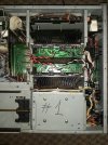
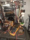
I am posting the photo of the parts involved into the swapping procedure.

All this parts on the photo was into the Amp#2d and they are working properly when was moved out and assembled to another amp #1.

All the parts : zobel filters,resistors ,capacitors , cables ...concerning the question in the post above are located here and they are involved in the swapping procedure.
Also see the picture from chapter 8 , post #141
OPS plus AMP board12.jpg
(sorry
i was not able to attach this in right position after long time fighting with the program)


On this place see the chapter 8 post #141.


#2d.jpg


#1.jpg

#4.jpg

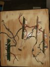
And here is a picture of the other parts that I use for the test rig. Thej have extended wires, but they are not into the ready working amplifiers:
20230626_002213.jpg


I also measured and indicated the length of the wires on the picture , according to questions above. All the wires are stock wires with a stock factory length. All the wires in all the amps I have are stock with the same stock length and no difference between them.
For the test rigs was used another set of driver plates and modified wires-on the picture here.

There was a question "Here is the wire and ground path, starting AT THE MAIN FILTER CAPS!!! "
Are the BIG CAPS ITSELF are possible to make this distortion or some filter capacitors on the power supply ?
 
Last edited:
we will save the power supply neutralization capacitors question for later.

Instead we need to see what resistors are in the dual (emitter) resistor R11 & R13 on the GWX-593, & R12 & R14 on the GWX-594
and are these any different than those resistors on the other working correctly (#1, #4 etc) chassis.

Overshoot is caused by inductance in the output / feedback path.
 
we will save the power supply neutralization capacitors question for later.

Instead we need to see what resistors are in the dual (emitter) resistor R11 & R13 on the GWX-593, & R12 & R14 on the GWX-594
and are these any different than those resistors on the other working correctly (#1, #4 etc) chassis.

Overshoot is caused by inductance in the output / feedback path.
I know for what you are talking about .View attachment 2919276

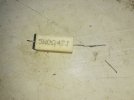
This resistors on the left are fake subs that inside has another ceramic resistor that has wire coil with 5 winds and can acting likes a coil for a high frequency . So thj are out of the game
we will save the power supply neutralization capacitors question for later.

Instead we need to see what resistors are in the dual (emitter) resistor R11 & R13 on the GWX-593, & R12 & R14 on the GWX-594
and are these any different than those resistors on the other working correctly (#1, #4 etc) chassis.

Overshoot is caused by inductance in the output / feedback path.
I know for what you are talking about:

20230626_165826.jpg

20230626_180127.jpg

20230626_180423.jpg

From the left side are the only available subs for this dual emitter resistors. But they inside has another ceramic resistor with a coil wire resistor. So they are inductive for a high frequency. But I was using them only on a test rig for testing. They are out of the game .

For all the amps I am using the original stock emitter resistors -this from the middle and from the right on the picture- so they are not inductive.

By the way, because was very easy I replace the big capacitors on Amp2d and make a test

20230626_163230.jpg.


The result is- NOTING CHANGED ,same picture, same distortion absolutely identical picture on the scope.. They are not the problem.
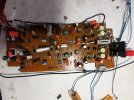
Another thing that catches my attention and therefore raises the suspicion of a possible defective capacitor is this EQ board. There are a million parts here. But I will wait here, because it is not clear to me whether the straight signal passes through capacitors at all. The redjack is connected to the AUX input. just for indication where is located the AUX.
May be here some bad capacitors?

20230626_164118.jpg
Actually this confusing me a lot- if is capacitor some where- there should be two capacitors for the L and R channel and they to be exact the same deteriorated to present the graphic on the scope that the both channels are with identical distortion. May be if we start from here will be easier.
 
Last edited:
Edit: I would compare the markings of those dual resistors very carefully to see if they are identical parts.


the definitive thing to do would be to trade those boards between the chassis...

see if that board, moved to a working chassis, presents symptoms.

I agree with the logic:
there should be two capacitors errors for the L and R channel and they to be exact the same deterioration to present the graphic on the scope that the both channels are with identical distortion.

Usually I look to the power supply (or an identical, repeated error) when BOTH channels are affected the same way.

neutralization caps in the power supply: (only two 0.01uf 400v mylars)

the A-9 power supply
GWR-141 AWR-226 series regulators are 2sb507p & 2sd313p 5 MHz transistors, 2sa912 & 2sc1885 are 200 MHz error amplifiers.
they use just ONE mylar 0.01uf 400v each (C3, C4 CQMA 103k 400) for + and - 60v regulated
This is the only regulated power used by the GWH-146 board.

I mention the transistor types, in case substitutions were made.
 
Last edited:
Edit: I would compare the markings of those dual resistors very carefully to see if they are identical parts.


the definitive thing to do would be to trade those boards between the chassis...

see if that board, moved to a working chassis, presents symptoms.

I agree with the logic:


Usually I look to the power supply (or an identical, repeated error) when BOTH channels are affected the same way.

neutralization caps in the power supply: (only two 0.01uf 400v mylars)

the A-9 power supply
GWR-141 series regulators are 2sb507p & 2sd313p 5 MHz transistors, 2sa912 & 2sc1885 are 200 MHz error amplifiers.
they use just ONE mylar 0.01uf 400v each (C3, C4 CQMA 103k 400) for + and - 60v regulated
This is the only regulated power used by the GWH-146 board.

I mention the transistor types, in case substitutions were made.
"the definitive thing to do would be to trade those boards between the chassis.." - Most likely the result from moving this board to be the same likes the moving of GWH-146.
There is not a part that affected the both channels in the same time in "line straight " mode.
This will be the last resort. Let's stick to the logic above.

I wish to be the GWR-141 -mylar cap. Let's check this first.
 
using faster transistor substitutes in the power supply regulator could be a factor, what transistors are in that circuit in that chassis, and are they in any way different from those in the other chassis? I mentioned those transistors as well as the capacitors.
 
"GWR-141 series regulators are 2sb507p & 2sd313p 5 MHz transistors, 2sa912 & 2sc1885 are 200 MHz error amplifiers."

There should be probably typo. I am assuming AWR-226 regulator assembly board where are located this transistors. I start to desolder the caps.
But on the Power supply board GWR-143 also we have 0.01uF caps and also 2SB507 and 2SD313 . Let me know if should perform action over there too.
 
GWR-143 caps do different things. they are across the transformer secondaries. Nowhere close to the problem.

AWR-226 is correct, the pdf i'm using is counter-intuitive and difficult to use accurately.
 
GWR-143 caps do different things. they are across the transformer secondaries. Nowhere close to the problem.

AWR-226 is correct, the pdf i'm using is counter-intuitive and difficult to use accurately.
BINGO!
Mark you are a genius! Again and forever!
It was a capacitor right there on the regulator board. This was C3 of GWR-226. Its value was 6.4nF instead of 10nF.

20230627_220520.jpg20230627_230224.jpg20230627_230750.jpg20230627_230838.jpg20230627_230904.jpg


"the pdf i'm using is counter-intuitive and difficult to use accurately."
I can email you pictures of the original service description of the schematics, as I sent to Qsilver. They are quite good, but the file is about 250 MB and must be sent to the email address you specify
 
BIG sigh of relief.:):banana::banana::jump:


I have an original paper manual that someday I might scan in and stitch together the multi-page diagrams. I just didn't dig it out for that post.
 
Last edited:
BIG sigh of relief.:):banana::banana::jump:


I have an original paper manual that someday I might scan in and stitch together the multi-page diagrams. I just didn't dig it out for that post.
:jump::banana::rockon::rflmao:

Thank you so much Mark!
I knew that with your invaluable help these amplifiers would be fixed. But I didn't imagine they could be repaired so well.
I really want to compare the quality of the repaired amps with the original as per spec to see if there really is any difference.
(I think that the repaired are better than the original)
But I don't know what exactly to measure to see if there is a difference in quality.
Unfortunately, I cannot measure THD with my instruments.
But still, is there any way I can compare them with scope and generator?
 
depends upon the scope model. IIRC it needs to have Fourier capability.

Yours looks to be HP 54610b, which would require additional measurement storage modules(54657a gpib, 546596b rs-232) to get FFT functions.

to that point and beyond I am not a guru.

there are plenty of instruments out there, just be sure it can go down to 0.001% or lower.

I use a Tektronix AA501 audio analyzer module.
 
depends upon the scope model. IIRC it needs to have Fourier capability.

Yours looks to be HP 54610b, which would require additional measurement storage modules(54657a gpib, 546596b rs-232) to get FFT functions.

to that point and beyond I am not a guru.

there are plenty of instruments out there, just be sure it can go down to 0.001% or lower.

I use a Tektronix AA501 audio analyzer module.
Scopes are usually 8-bit or 10-bit resolution, not good enough for low thd measurements
Yes, understand what it's all about after seeing what AA-501 is.
Scope and generator is not enough.
I played around with the scope to catch some difference or visible distortion between all the amps, but I couldn't find any.
I couldn't even see a difference between a biased and an unbiased channel on the same amp ( xraytonyb also shows this on Yoу tube by the way. But he explained it with the very good selection of complementary pairs, the amp was also NSA)
The original power amplifier and the repaired ones do not differ in any way. It turned out that the RET transistors are in no way inferior to the modern ones and in terms of power they are even better.

Especially in terms of the quality of the music, which is the most important to me . they do not differ at all.
 
Hi all,
Wonderful job done here so far.
I have a very simple question:
I own 3 pioneer's, one A-7 and two A-9's working great so far with no repairs whatsoever.
Is there any previous service to do before anything starts to fail?
Thank you all.
 
Back
Top Bottom