

You are using an out of date browser. It may not display this or other websites correctly.
You should upgrade or use an alternative browser.
You should upgrade or use an alternative browser.
Replacement for NEC B537 L64C transistor
- Thread starter Zekeman
- Start date
Register to hide this ad


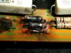
It appears that the base (I believe) of theTR17 (MJE15031G) was shorted thereby frying D05 and the R45 TR09 as far as I can tell.
I replaced the TR17, D05, R45, R57 (it was cooked by the resistor next to it), TR13, and TR09. I powered it up with the dim bulb and it is indicating problem.
Question for you; Since I am just going to go ahead and replace caps, diode (VD1212's) and fuse resistor the entire power board what else was likely damaged by this shorting of the base?
See pix.
I replaced the TR17, D05, R45, R57 (it was cooked by the resistor next to it), TR13, and TR09. I powered it up with the dim bulb and it is indicating problem.
Question for you; Since I am just going to go ahead and replace caps, diode (VD1212's) and fuse resistor the entire power board what else was likely damaged by this shorting of the base?
See pix.
Attachments

Last edited:

petehall347
the brandy coffee man
TR19 is giving me 0.16 voltage readings. It is an
NEC D388A (1) R63
on b c or e or all ? ac or dc ?

...yea from 2009
http://www.audiokarma.org/forums/showthread.php?t=269996
So with a voltage reading like that I note above (0.16) the output is toast right? ...and if so, should I replace only that ONE transistor or should I replace the pair of this type in this one channel....or should I replace all four trannies in this channel?
Thanks.
http://www.audiokarma.org/forums/showthread.php?t=269996
So with a voltage reading like that I note above (0.16) the output is toast right? ...and if so, should I replace only that ONE transistor or should I replace the pair of this type in this one channel....or should I replace all four trannies in this channel?
Thanks.
Last edited:
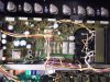

In power amplifiers this is a technique used to spread the current passed by the output devices to achieve a higher power output than from just 2 pairs of devices (assuming stereo). Originally this may have been due to the limitations of the devices themselves - and was the only way a certain power level could be achieved.
In lower power amplifiers better thermal stability and reputedly lower crossover distortion are the result of this. Originally these transistors may have been matched to ensure correct load sharing. The inclusion of series base resistors and the all important emitter resistors also helps with this. Now, transistor fabrication has improved so much that the requirement to match output transistors is almost unnecessary. Only now suggested when you have a very high power amplifier with low value emitter resistors. (lower than we normally see anyway). Add to this, the current carrying capability and power dissipation that individual power transistors (TO3 devices) can withstand has also increased.
Nice pic of the inside of the '7900 never seen the inside of one - thanks
In lower power amplifiers better thermal stability and reputedly lower crossover distortion are the result of this. Originally these transistors may have been matched to ensure correct load sharing. The inclusion of series base resistors and the all important emitter resistors also helps with this. Now, transistor fabrication has improved so much that the requirement to match output transistors is almost unnecessary. Only now suggested when you have a very high power amplifier with low value emitter resistors. (lower than we normally see anyway). Add to this, the current carrying capability and power dissipation that individual power transistors (TO3 devices) can withstand has also increased.
Nice pic of the inside of the '7900 never seen the inside of one - thanks
Last edited:
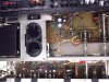
Already replaced TR13 just because it was in the initial line of fire. I'll go ahead and replace TR 15 and 11. The other outputs on that channel tested OK. I have a shipment from Mouser on its way with new outputs since TR 19 was toasted. So if I understand you correctly, should I replace all four TO-3 outputs on this channel so as not to mix old and new as well...?
Last edited:
Already replaced TR13 just because it was in the initial line of fire. I'll go ahead and replace TR 15 and 11. The other outputs on that channel tested OK. I have a shipment from Mouser on its way with new outputs since TR 19 was toasted. So if I understand you correctly, should I replace all four TO-3 outputs on this channel so as not to mix old and new as well...?
A good idea - remember the old ones won't match too well with the new ones.
And, a channel with all old outputs should audibly be indistinguishable from a channel with all new outputs.
Last edited:
TR11 is a 2SC 1951 which is the complement to TR 13 (which I already replaced with a KSA 916). The KSA 916 spec sheet states that its complement is KSC 2316 and Mouser lists it as not available!?!? How can they carry one and not the other? Can anyone suggest another component?
==============================
Update: In another post LB Pete states that the ZTX 694B is an almost exact match
http://www.audiokarma.org/forums/showthread.php?t=290465
...if anyone can confirm that this is the case please advise.
Thanks.
==============================
Update: In another post LB Pete states that the ZTX 694B is an almost exact match
http://www.audiokarma.org/forums/showthread.php?t=290465
...if anyone can confirm that this is the case please advise.
Thanks.
Last edited:
OK here's the scoop:
I recapped all electrolytics on the entire board (not the ceramics).
Replaced all VD1212 diodes
Replaced the fusible resistors
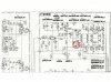
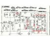
Replaced the following transistors: (See pic also of all components replaced circled in red...I put a red explosion graphic where I believe the original short occurred)
TR 7,9 13 15,17 19,21 23,25
I tested all emitter resistors and all are OK
Replaced the relay
After all this my dim bulb tester still lights up like a damn Christmas tree!!...so any advice on what may be the next steps in troubleshooting this short would be greatly appreciated.
======================================================
Also...What would be the best replacement here for the 2SC711 ... in another post Markthefixer identified three possible replacements:
2SC711 - 30v; 100mA; 0.2W; 150mhz; TO92L
512-KSC1845EBU (ln)to-92 ecb 120v .05a .5w 100mhz 150-800hfe
512-KSC2310YBU TO-92 ecb 150v .05a .8w 100mhz 40-240hfe
512-KSC945CLTA to-92 eCb 50v .15a .25w 300mhz 40-700hfe
I recapped all electrolytics on the entire board (not the ceramics).
Replaced all VD1212 diodes
Replaced the fusible resistors
Replaced the following transistors: (See pic also of all components replaced circled in red...I put a red explosion graphic where I believe the original short occurred)
TR 7,9 13 15,17 19,21 23,25
I tested all emitter resistors and all are OK
Replaced the relay
After all this my dim bulb tester still lights up like a damn Christmas tree!!...so any advice on what may be the next steps in troubleshooting this short would be greatly appreciated.
======================================================
Also...What would be the best replacement here for the 2SC711 ... in another post Markthefixer identified three possible replacements:
2SC711 - 30v; 100mA; 0.2W; 150mhz; TO92L
512-KSC1845EBU (ln)to-92 ecb 120v .05a .5w 100mhz 150-800hfe
512-KSC2310YBU TO-92 ecb 150v .05a .8w 100mhz 40-240hfe
512-KSC945CLTA to-92 eCb 50v .15a .25w 300mhz 40-700hfe
Attachments
Last edited:
Replaced TR 11 and 13 with 694B's (EBC pinout watch out!) and it sounded fantastic...
However I adjusted the bias and I got no bias curent in the channel with the new outputs. TR 5 (2SC711) did not test correctly between the base and collector so I replaced TR5 with a KSC 945 CLTA and the dim bulb now goes bright initially, then pulsates bright and dim repeatedly.
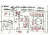
Pic of components replace so far...attached
==========================================
edit: Solution is to install TR05 with the flat opposed to the heatstink which is opposite to the original.
However I adjusted the bias and I got no bias curent in the channel with the new outputs. TR 5 (2SC711) did not test correctly between the base and collector so I replaced TR5 with a KSC 945 CLTA and the dim bulb now goes bright initially, then pulsates bright and dim repeatedly.
Pic of components replace so far...attached
==========================================
edit: Solution is to install TR05 with the flat opposed to the heatstink which is opposite to the original.
Attachments
Last edited:


