• The move to the new server is done. There are some software and database maintenance updates in process. This has us passing the hat around to help out. We appreciate any donations. Seriously, even a dollar helps. The payment page may be found here - https://www.audiokarma.org/support.html

SA-8800 Oscillation?

But did you recap it due to a problem or did the problems start after recapping.

The drivers may have run hot for a long time but it is possible that they were fine.

As I read your description when smoke came out one channel failed, how did
the second channel fail?

It had a lot of problems and I recapped it while I repaired the other faults. Someone has been in before me and screwed up the power supply board. Incorrect zener diodes and regulator transistors.... The pre-amp was dead because of the regulator board so when I got that working I re-capped it too - there's not many in there and looking at the blown zeners and general condition, I'm pretty sure the drivers weren't good. They were very black and as I said. One on the bad channel was oscillating and breaking down periodically which is what probably knocked out the output transistor. The smoke was caused my a 220 Ohm resistor.

It worked well for a week or so and then started to slowdown coming out of protection. I hadn't been able to use it much prior to that as the pre-amp was dead. Everything was looking very tired.

The second channel didn't fail per se. But once the other channel blew and started to oscillate, so did the other.

Thinking back now, I might've said this already, but I think it was Channel 2 (R) that blew, the one that now has the slight high frequency waveform so although it's "stable" perhaps there is still something not right somewhere.... if there is, it might be the ceramic caps as most of those on testing are towards the edges of the 20% margin and I've heard of ceramics going microphonic also... but maybe I'm making too much of it.

Are you able to make this measurement?

To a point. I have a Radford D.M.S. Series 2.

me too but my time is limited on this one.

I would suggest to add a bleeder R and a 1u/100V poly film across the big ecaps.

I had thought about 2.2uF maybe 10k for a bleeder?
 
It's a very old Distortion Measuring set but does go down to 0.001 IIRC. What should I try it at first? 10W? I don't have anything to run it into clipping at the moment, I'll have to buy a load or two.

I tried changing R121 from 75 Ohm to, at first 470 Ohm and it went straight back into oscillation... I next tried 150 Ohm and it doesn't oscillate, the voltage drop across R121 seems mostly unchanged compared to 75 Ohm at 1.23V.

I think it is easier to adjust the bias now and the drivers run at 35-40°C.

Although, channel 1 did do something reminiscent of when it failed... The DC offset suddenly jumped and the amp went into protection. It was on a DBT and the DBT didn't start to glow so no current draw... I quickly powered off, then powered on and everything was then okay. However, if I direct a blast of cool air into the channel 1 area, the DC offset starts to rise into the positive. The same treatment to channel 2 seems to do the same, although not as much of a drift...

Not sure if I am knit picking, or if there is something not quite right here.... :idea:
 
1W/10W loads are valid measurements to take.
at first 470 Ohm and it went straight back into oscillation.
Interesting and with what ?pF of FB compensation?
I think it is easier to adjust the bias now and the drivers run at 35-40°C.
Good
Do you have the i/p bjts thermally coupled to each other, this may help. i recall a pic showing them (ksa992) sitting side by side. Are the original a979 toasted?
Not sure if I am knit picking, or if there is something not quite right here.... :idea:
yeah I agree, it not the best behaved design is it?
 
1W/10W loads are valid measurements to take.

Roger, I'll bypass the pre-amp too.

FB compensation is still just the stock 39pF cap. I'll get something nearer to 82pF this week if I can. The oscillation was less random this time however and more like a Sine wave with bad crossover points. I only changed R121 and NOT the same resistor on channel 2. Despite this, Channel 1 went into some big oscillations and seemed to induce a smaller copy of the oscillation onto channel 2. On the scope, channel 2 was full visable at maximum sensitivity and channel 1 was about 3 or more times off the scale.

Good point about the i/p bjt. I do still have the originals and they are probably okay. I removed them for resting purposes.

It really isn't behaving... I did just fix a problem on an SX-V80 recently that I've had for a few years. I took the top off today to check it over and check the idle current. It too, is an NSA that I have worked on. It was very easy to set the idle current up properly, runs cooler, uses less o/p bjts. I also looked that the schematic for the SX-D5000 and yes, it does look pretty similar to the SA-8800. Either way something isn't just 100% with this one... even if it was all exact replacements of the drivers/ouputs I have a feeling it would still be screwing around right now...
 
Have to agree with you but what to do, we did a small amount of re-design, just to get it sort of working again, so do we continue to re-design the PA section?
Sometimes it is better to start from scratch than having to fix something that has problems. It involves a fair bit of work however.
 
I've laid it flat today and tried to bias. Seems to be easier to bias to 70mV now. I'm looking for 82pF caps for the feedback loop but so far only found one candidate so I'll keep looking. Wondering if the resistor on the feedback loop could cause problems. Its one of those wire wound red ones Pioneer use in places....

I took some measurements of distortion. It seems my audio generator measured out at 0.045THD @ 1kHz so I suppose that will be the measurement floor...

Left it to idle at 70mV for a good hour and then put an 8 Ohm load on.

1W (on the VFD) 2.63V. Idle current went up to 109mV. 0.16% THD @1kHz

10W (on the VFD) 8.95V Idle current now at 266mV. 0.06% THD @1kHz

How is that looking? My distortion analyser does have lower THD scales but I'll need a low distortion source to go finer I suppose? Does the idle current look normal? I know its no longer "idle" but its the same test point...

After these two tests, the idle current sat at 83mV, probably because it warmed up a bit but I readjusted for 70mV again on VR9...
 
The THD measurements are high in comparison to the specs and sims. I am not sure why that is.
Bias should only be set/measured with no i/p signal.
The FB R's should not be w/w type, they should be low inductance metal film types.
Where are you looking for a 82pF cap, you can parallel to 39pF caps, that will do. But before you do that, look at a square response on the scope with the 8 ohm loading. Run a 20KHz square into the power amp i/p jack.
 
Fair enough about bias.
Maybe they are metal film but I think these ones are wire wound. here's a picture of it...
Looking for it from RS and Farnell. Though not looked at Farnell yet...

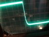
Put the square wave through at, from what my DMM tells me are the same voltages and got the below results. I zoomed in on the trailing edge of the square wave - a slight wiggle but nothing major here. I did tentatively run it up higher and I didn't get any real severe ringing, just a slight sloping off of the initial peak of the square wave.
 

Attachments

  • 20180423_171157.jpg
    20180423_171157.jpg
    58.3 KB · Views: 26
  • 20180423_171018.jpg
    20180423_171018.jpg
    50.9 KB · Views: 27
  • 20180423_170950.jpg
    20180423_170950.jpg
    58.3 KB · Views: 28
  • Feedback.jpg
    Feedback.jpg
    108.4 KB · Views: 29
BW limit for scope on or off? should be off, looks fine as it is, high pF comp cap will just round it off some more.
That R looks like it is a metal film type.
 
Ok, so all good on those tests for now?

BW limit? It's a CRT scope, sweep range was 20kHz to 100kHz. Supposedly this is a 5MHz scope but I wouldn't mind a better/faster one...
 
I've used it for a while now and it seems stable enough. I've hooked it back into the distortion meter and I get 0.05% THD on both channels at 10W. So this seems a bit off... I was thinking of revisiting this a little and trying some adjustments. Looking at the NSA amp in the SA-9800, the amplifier looks to be very similar but I notice the feedback path has 82pF and 2.7kR as opposed to the SA-8800 39pF and 2.2kR. Could we feed these into the simulation if you are willing to entertain the idea RCS16? I could try to run the simulations myself but I do not yet know how to run simulations on Spice.

I was also thinking of trying different driver transistors such as the 2SA940 and the 2SC2073 (IIRC) I have some of these that I could try out.

Also, is there a point in the amplifier that the second idle current adjustment can be seen to take proper effect? As I'd like to try and confirm that the NSA section is coming up correctly when adjusted.
 
Last edited:
Sorry no time to do any sims, Mom is sick in the hospital.
I did sim the SA-9800 as well iirc. SA-9800 has more gain so that would explain the f/b value differences. i recall a bit of difference in the bias gen ckts as well, but it has been a while so I forget the details.
If you put in the 2SA940 and the 2SC2073 I think it may throw the bias off again, so not sure if the values we chose would work again. I have no sim models for 2SA940 and the 2SC2073.

Good Luck
Rick
 
Thanks for your input and I'm really sorry to hear about your Mom. I wish her and yourself all the best.

I've tentatively tried changing one amp channel, the left channel around for experimentation so I'll document what I got so far.

To begin with, the amplifier in the state it was in post #114, the second idle current adjustment is difficult and has to be near fully turned to achieve 72mV.

What I did next was as follows.

1) Turn all bias adjustments to minimum (0mV)
2) Replace the drivers MJE15032G & MJE15033G with the 2SA940 & 2SC2073 as well as changing R121 from 150R back to 470R
3) Powered up and found that I could get no idle current at all. 0mV almost all the way round the first adjustment.
4) I decided to replace the transistor used in place of the bias diode, STV-2H, back to the original STV-2H.
5) Powered back up again and the idle current can be set to 56mV very low down on the first adjustment (probably too low down).

At this point, the second adjustment for idle current responded well and much like the amplifier did originally. I adjusted the amp to 56mV and then 72mV and allowed it to idle and then drove it into an 8R load at 10W and the amplifier remained thermally stable so this seems to be interesting. Oscillation did not occur.

The downsides are:

1) The initial idle adjustment is now probably overly sensitive.
2) The THD measurement at 10W did not change and remained 0.05% THD. However I'm going to investigate my audio generation source as recently I had the same source outputting a signal down to the 0.000% scale and lower on a pre-amp....
 
Hello guys. The SA 8800 amp had a DC leak and it has been taken care of . I made the balance adjustment, everything is as it should be in both channels 0V set ok. However, there is no problem in the idle current setting Left and I saw and set 56Mv at test points. I'm not reading on the right channel. While testing the device, there is interference in the low frequency song test on the Right channel. I changed the trimpot but still the same. I replaced the output transistors completely, they are still the same and nothing changes the fault location. Could large capacitors in the supply circuit cause this? Thanks (
Tone solid is completely disabled)
 
Hi Folks;
Thanks so much for all the interesting info about the SA-8800. I have one on the bench that had an oscillation problem. It turned out to be an open R1, a 10 ohm resistor right beside the speaker relay. I should have checked that first! It was showing signs on overheating. Oscillation was in both channels but replacing this one resistor solved the issue on both sides.
Unfortunately, I'm still dealing with a channel imbalance. The left side is low. I have traced it to the volume control itself, as far as I can tell; L is low at half volume but balanced at full volume....
 
Hi Folks;
Thanks so much for all the interesting info about the SA-8800. I have one on the bench that had an oscillation problem. It turned out to be an open R1, a 10 ohm resistor right beside the speaker relay. I should have checked that first! It was showing signs on overheating. Oscillation was in both channels but replacing this one resistor solved the issue on both sides.
Unfortunately, I'm still dealing with a channel imbalance. The left side is low. I have traced it to the volume control itself, as far as I can tell; L is low at half volume but balanced at full volume....
i believe those 10 ohm resistors are anti oscillation resistors so aren't the problem .mine has had same problem for years ..its still sat on my bench for more testing . it burned out on mine because i was playing different waveforms through it with my signal generator . that must have damaged something else because it still burns the resistor in normal use
 
Back
Top Bottom