• The move to the new server is done. There are some software and database maintenance updates in process. This has us passing the hat around to help out. We appreciate any donations. Seriously, even a dollar helps. The payment page may be found here - https://www.audiokarma.org/support.html

Sansui AU-217 Restoration

Ok, this thing deserves a shout from the rooftops. I gave it a proper listening today and was stunned by the sound: clear as a bell, effortless, and bass that can only be described as perfectly executed. You know things are going well when you start digging out old CDs and just stand there at the bench, listening and listening and then it's time for dinner but you feel like you could keep listening all night. This is one of my more modern amplifiers and I was impressed when I put my ear right to the speaker cones and could not hear a bloody thing--as Oak Tree Vintage Audio often claims, it's dead silent. DC offset is too low to even sniff at and folks, I looked again and I cannot find one IC in this amplifier. Good old TO-3 output devices on a thick aluminum heat sink. At 17" wide it matches up nicely with most of the 80's source gear, including digital tuners and cassette decks. It's even simpler than my desert island pick, the Sherwood S7100A, as that has the notorious OFF/ON/VOLUME pot, as well as an ancient FM section that's not going to last forever, let's face it.

So, easy to work on, dead simple (and should prove to be utterly reliable), dead silent, and oh, the SOUND. And nobody wants 'em. My gain! Hell of an amp.
 
Hi there. That Leestereo amp looks sweet.
I've been sucked back in the hobby after many years. So I grabbed a pristine AU-217 and really liked the sound. Deep bass and somehow "valveish" signature. A little muddy but sweet.
There were some issues tough. The scene presentation was not great and there were some more problems with the phono input (seemed a weak transistor somewhere) and the noise floor was somehow high.
In a sentence, compared to a most recent Pioneer A-109 the A217 felt less tidy and much warmer.
Next thing I know, I was ordering caps and transistors and my recap journey begun. Little I knew that I was up for a major disappointment and in desperate need of help (keep reading).
In order, I swapped all electrolytics on the amp board while powering it up from time to time for a sound check.
On the power board I used Panasonic FM for almost everything, except the 47uF which were FC, the 1uF 50V were Nichicon Gold. Here's a list.
  • C01 1 uF 50 V - Replaced
  • C02 1 uF 50 V - Replaced
  • C27 1 uF 50 V - Replaced
  • C28 1 uF 50 V - Replaced
  • C602 1 uF 50 V BIPOLAR Replaced
  • C621 3.3 uF 50 V - Replaced
  • C622 3.3 uF 50 V - Replaced
  • C11 47 uF 6.3 V - Replaced
  • C12 47 uF 6.3 V - Replaced
  • C601 47 uF 6.3 V BIPOLAR Replaced
  • C07 47 uF 50 V - Replaced
  • C08 47 uF 50 V - Replaced
  • C605 47 uF 50 V - Replaced
  • C23 100 uF 6.3 V with 100uF 25V Replaced
  • C24 100 uF 6.3 V with 100uF 25V Replaced
  • C25 100 uF 6.3 V with 100uF 25V Replaced
  • C26 100 uF 6.3 V with 100uF 25V Replaced
  • C608 100 uF 50 V - Replaced
  • C609 100 uF 50 V – Replaced
  • C610 100 uF 50 V - Replaced
  • C611 100 uF 50 V - Replaced
  • C09 330 uF 50 V - Replaced
  • C10 330 uF 50 V - Replaced
  • C15 330 uF 50 V - Replaced
  • C16 330 uF 50 V - Replaced
  • C29 470 uF 6.3 V with 470 25V Replaced
  • C30 470 uF 6.3 V with 470 25V Replaced
  • C604 470 uF 6.3 V Increase to 2200uF Replaced
  • C606 470 uF 50 V - Replaced
  • C607 470 uF 50 V - Replaced
  • C612 6800 uF 50 V - Replaced
  • C613 6800 uF 50 V - Replaced

An important note: My cap datecodes were all between '74 and '78. The amp I think is around '78-'79. Almost all caps coming off the board measured perfectly fine. Some had even lower ESR than the new ones I put in. That is very puzzling as all new caps were new purchases from a reputable distributor (RS-components).

I also swapped out some transistors. They were mostly strong, all measuring above 400. I swapped out
  • TR03, TR04 from 2SA276 to KSA992FTA (matched hfe 454)
  • IC01, IC02 from 2SA798 to 2xKSA992FTA (matched hfe 454)
  • VD1212 swapped for 2x1N4148
I did not touch other transistors there.

In parallel I was working on the phono board. Here I found a weak trans and a shot electrolytics (TR01 was measuring around 200). The rest was fine. Here's the list:
  • C01 1 uF 50 V REPLACED
  • C02 1 uF 50 V REPLACED
  • C05 100 uF 6.3 V REPLACED with 100uF 16v (old stock ~2005. measuring fine)
  • C06 100 uF 6.3 V REPLACED with 100uF 16v (old stock ~2005, measuring fine)
  • C13 47 uF 10 V REPLACED
  • C14 47 uF 10 V REPLACED
  • C15 3.3 uF 50 V REPLACED rubycon yxf (good enough?)
  • C16 3.3 uF 50 V REPLACED rubycon yxf (good enough?)
  • C617 220 uF 35 V REPLACED
  • C618 220 uF 35 V REPLACED
  • C619 220 uF 35 V REPLACED
  • TR01,02 2SA726 REPLACED KSA992F 1 x hfe 200. New replacement mathced with hfe 484
  • TR03,04 2SC1400 REPLACED KSA1845 HFE432

What I was thinking: I was trying to lower the noise floor of the amp, that was somewhat high to start with. Certainly the SNR of the Sansui was much worse than the Pioneer A109 and definitely worse than my other references (a Fiio M3 Pro DAC/Player, a Behringer UMC Pro DAC/ADC and some other random modern electronics, all with SNR well above 100dB). For the listening, I'm using some headphones (Sennheiser HD599/HD600 and some reference iem monitors too). For speaker reference I'm using some JBL Class-D studio monitors (the LSR305) and the PA attached to the sansui are JBL4312.

What did I found? The bass seems to have dried up. There seems to be much less bass and it looks much more controlled now. It's faster, tighter but there's not enough of it. The mids and highs seem to have opened up. Voices (female voices specially) are clear and present. The highs are brighter but somehow not as sweet as before. It definitely does not sound so valveish now and is much closer to the A109 and the LSR305.

In the headphones, I hear the same thing. The bass is somehow recessed, faster. The extension is lower than on speakers. Maybe I have a cap issue (not enough juice on the new caps?). Or perhaps the headphone extension goes way lower than my speakers. The Au217 drives the headphones from the same outputs stage as the PA so the sound signature should be the same.

In a word: I'm afraid I broke it. The famous Sansui sound seems lost. It feels like a normal amp now. Nothing special. What is worse, the noise floor is still high. There was an improvement, but not as much as I'd hoped for.

Any idea what could have caused this? Was it the rework of the phono board or the new transistors I put in the phono or in the main amp board? Where do I start looking?
Also, where shall I look to lower the noise floor more? It's OK when listening to music, but on low passages, when the volume knob it turned up I can hear it? Think Pink Floyd intro to the Dark Side of the Moon, or Telegraph Road / Dire Straits. There's more noise that I'd like to hear.

Last but not least: I do have some (very low) 50/60Hz hum coming in. It seems generated on the tone and phono board. I tried re-grounding cleaning and re-tighten all screws and have made some (little) difference. Still too much hum compared to more modern references. Are there any known "issues" with the 217 here?

Thanks for reading all this blob I wrote. I hope I get some answers or hints.

JackE

 
Last edited:
@JackE: the AU-217 has some fuse-resistors that should be replaced with equivalent value metal film types, i.e., R39-R46. Is the perception of a lack of bass response on line and phono sources? What is the bias set to? Is the AC mains wiring bundled with the wiring to the headphone jack/speaker switch?
 
you probably need more time on the new caps - run it for a 100 hrs and report back on what you hear - bet it improves.
 
@Leestereo: Oops, forgot to mention that the fuse resistors were changed first thing, together with the VD1212 dual diode. At the same time I also changed the bias trimmers (VR01,02) with some multi-turn precision trimmers. The bias was 6.5mV when it came to me, and now it's 7mV. They're quite stable after warm up, around +/- .1mV from the set point.

The lack of bass seems generalized, but I only tested the Tuner/Aux/Tape inputs, using the m3Pro which is battery powered and plays DSD files. There's a slight volume difference on the Tape input which should be due to the R03/R05 partition on it. I have yet to attach it to a record player and check the phono input. Maybe all this is psychoacoustic and I need to take some measurements, before going on. Maybe 100hours of burn-in is overkill but a day or two with the power switch on will do it.

Regarding the hum you might be right. The AC wiring runs with the wiring of the speaker relay, between the transformer and the main board. I think that is very weird. Would you suggest me to reroute the two away from each other?

I hope to be able to measure the power output and stability today or tomorrow, and I'll report back my findings.
 
...The bias was 6.5mV when it came to me, and now it's 7mV. They're quite stable after warm up, around +/- .1mV from the set point.

IMO, at 21mA, the factory spec. for the bias is somewhat conservative, consider increasing it to 30mA; for more accurate bias reading, measure across both emitter resistors (access to these is actually better than the bias test points buried inside the heatsink).

...The lack of bass seems generalized, but I only tested the Tuner/Aux/Tape inputs, using the m3Pro which is battery powered and plays DSD files...Maybe all this is psychoacoustic and I need to take some measurements, before going on...

The lack of bass perception may be due to the shift in the sound balance, e.g., increased clarity of the midrange/treble. This shift is not uncommon following the replacement of the aged stock capacitors; the measurement of ESR at a single frequency (often 1kHz) may not be indicative of the increased ESR at higher frequencies (this would be particular relevant for signal path/coupling capacitors).

Regarding the hum you might be right. The AC wir to 20Hzing runs with the wiring of the speaker relay, between the transformer and the main board. I think that is very weird. Would you suggest me to reroute the two away from each other?

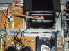
The AC wiring to the power switch should be moved to the other side of the transformer and the transformer wires from the secondaries should be separated from the speaker/headphone wiring.
 
IMO, at 21mA, the factory spec. for the bias is somewhat conservative, consider increasing it to 30mA; for more accurate bias reading, measure across both emitter resistors (access to these is actually better than the bias test points buried inside the heatsink).
I'm measuring across R49/R50 directly. My inexperience shows. I misread the service manual. 7mA should have felt too small. It is 21mA as you pointed out. Ouch!

The lack of bass perception may be due to the shift in the sound balance, e.g., increased clarity of the midrange/treble. This shift is not uncommon following the replacement of the aged stock capacitors; the measurement of ESR at a single frequency (often 1kHz) may not be indicative of the increased ESR at higher frequencies (this would be particular relevant for signal path/coupling capacitors).
I agree with you. The amp had a much darker signature before the recap. It's more neutral now. I don't believe in long period burn ins, but I left it on overnight so that all new caps could warm and settle up a little. The difference can be already felt and the bass extension is coming back. It still sounds better with the loudness switch on tough.

The AC wiring to the power switch should be moved to the other side of the transformer and the transformer wires from the secondaries should be separated from the speaker/headphone wiring.

So, this will be the small project for the weekend. I hope the wires will be long enough and I'll not have to rewire it totally.

Meanwhile, I was able to connect the phono stage to my other project (a PL518X) and check it. I like it a lot. The old rubycon yxt caps I had were not a bad choice after all and I don't feel the urge to move to polypropylenes yet.

I'll come back as soon as I rewire the AC wiring, I hope with more good news.
 
...The amp had a much darker signature before the recap. It's more neutral now. I don't believe in long period burn ins, but I left it on overnight so that all new caps could warm and settle up a little. The difference can be already felt and the bass extension is coming back. It still sounds better with the loudness switch on tough...

Prior its restoration/upgrade, my AU-217 also had a "dark" sound signature, akin to a downward sloping of the high frequency response in the last 2 octaves (i.e., 5-20kHz), as if a High Filter was engaged. The mid-bass response did "firm up" post restoration, which can also contribute to the impression of less bass; I actually found that the bass extension improved (bass notes <40Hz were better rendered).

...So, this will be the small project for the weekend. I hope the wires will be long enough and I'll not have to rewire it totally...

The AC wiring should be long enough to avoid having to do any re-wiring; also elevate the transformer secondary wiring away from the main board.
AU-217 AC wiring.jpg

...Meanwhile, I was able to connect the phono stage to my other project (a PL518X) and check it. I like it a lot. The old rubycon yxt caps I had were not a bad choice after all and I don't feel the urge to move to polypropylenes yet.

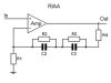
The AU-217 (and AU-117) phono stages use a different/older RIAA equalization topology from the other integrated amplifiers (i.e., AU-317-717) in the series. In the latter amplifiers, the RIAA feedback circuit employs a set of parallel RC pairs; this topology can provide very accurate RIAA equalization and essentially became the de facto standard in the late 70s. The stock AU-217 RIAA circuit can be modified relatively easily to this type; I can provide additional details if you wish to do this for your AU-217.

RIAA block diagram.jpg
 
The AU-217 (and AU-117) phono stages use a different/older RIAA equalization topology from the other integrated amplifiers (i.e., AU-317-717) in the series. In the latter amplifiers, the RIAA feedback circuit employs a set of parallel RC pairs; this topology can provide very accurate RIAA equalization and essentially became the de facto standard in the late 70s. The stock AU-217 RIAA circuit can be modified relatively easily to this type; I can provide additional details if you wish to do this for your AU-217.
I have not decided if I'd like to use the 217 as a test bed for some modifications, or if I'd like to keep it as close to the original as possible. I saw your phono mod on the AU555 restoration thread. I am surely tempted to do something similar on the 217.
But I have to hunt that hum down first ;)
 
So, I got some quality time with the AU-217 and the Pioneer A109 and was able to measure them both.
The AU-217 puts out about 38W rms per channel (not bad for a 30W amp) while the Pioneer clips at 40.1W rms per channel (being a 40W amp).

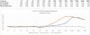
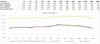
Then I made some measurements for the frequency response. I put a pure resistive load on the outputs and used a pure sine wave generator as input at 1vpp and different frequencies. I measured the output volts across the resistive load using a scope. The numbers are volts rms versus frequency. Here's the chart:

freq.jpg

And, yes, there's a problem with the Sansui. It is somewhat linear up to 1K then loses it and the treble is obviously problematic.

I could use some help in diagnosing it.
 
Definitely something is off. Surprised that the 2 line level inputs show different behavior, i.e., Tape vs. Aux input. The only difference between these inputs is the presence of a voltage divider (1kohm/1Mohm) on the Tape input. Does the tuner input show the same behavior? What if you lower the input signal? Were in components replaced in the feedback loop? Note that the tone controls in the AU-217 are also in the feedback since there is no active preamplifier stage per se.
 
I agree, that both responses should be flat. Something looks funny on the au217 data. But you may need to plot the ratio volts_at_output/volts_input
This eliminates the posibillity of a fluctuation due to the amplitude variation of the sine wave signal.
Also, your plot supresses the zero on the vertical scale, which makes the difference be exagerated a bit.
 
So, on a double-read of the service manual, it calls for 7mV bias +/- 0.5mV. Not sure how it affects the frequency response. To be on the safe side, I put it back to 7.5mV on both channels.
I rerouted the AC lines away as Leestereo suggested and the hum has improved quite a bit. Thanks for that hint!

The freq.response issue I had is under control, now. It seems that I'm dealing with a simple case of dirty pots. They were cleaned before the recap but they could use some ultrasonic treatment and disassembling. I noticed that my measurements changed when I was playing with the tone controls and did not always measure the same at "0" after moving them around.
For now I cleaned them as much as possible with contact cleaner and things have improved (chart below).

I found out that the bass pot is only 16.8K while the schematic calls for 100K on both bass and treble. The treble is 100K. I'm not sure if and why it was changed, or if it came like this from the fab.

Here's the updated chart. The Y axis does not start from 0 so that we can appreciate better the curve. I see light at the end of the tunnel. Thank you all for the hints.

freq2.jpg
 
So, on a double-read of the service manual, it calls for 7mV bias +/- 0.5mV. Not sure how it affects the frequency response. To be on the safe side, I put it back to 7.5mV on both channels...

The bias current wouldn't affect the frequency response (unless something else is awry). Increasing the bias to 30mA (20mV reading across 0.33ohm+0.33ohm) would minimize the distortion without heat-stressing any component.

The freq.response issue I had is under control, now. It seems that I'm dealing with a simple case of dirty pots...For now I cleaned them as much as possible with contact cleaner and things have improved (chart below).
Looks much improved now; at least it was an easy fix.

I found out that the bass pot is only 16.8K while the schematic calls for 100K on both bass and treble. The treble is 100K. I'm not sure if and why it was changed, or if it came like this from the fab.
This does seem strange, are the markings on the pots different?
 
over the years, I have rebuilt three of the 217s. would agree, they are quite the sleeper amp if used within their power range. One of the 217s sees 24/7 duty as my power amp for the PC speakers. To the original poster, don't forget to remove all that infamous Sansui glue. As it ages it becomes corrosive. On one of the 217's the glue had eaten completely through the positive main filter cap lead. Also lots of bypass upgrades can be done to this. If I can find the photos would post.
 
Yes, the pots are the labeled the same. I'm measuring in-circuit. Should be OK, but maybe it's making a parallel with something else off-board via R13, R53 or there about. Shall I go on and desolder it ?

bass-treble-pots web.jpg
 
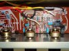
IMO, it's unlikely that there's anything wrong with the bass control; the 16.8kohm measurement is an artifact of measuring in circuit. Here's a picture of bass and treble controls in mine.
Tone controls restored.jpg
 
Back
Top Bottom