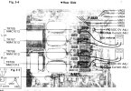
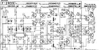
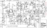
I don't have a clearer version of that picture either, but I have done the adjustment many times, so I can give you some pointers that may help you.
To measure the bias current you need to find the emitters of the output transistors, and connect your multimeter probes to them, remember you will be measuring a voltage. Looking from the top of the unit down into the heatsink channel where the transistor pins and emitter resistors are, you should be able to find the two emitter connections - one for each of the top two output transistors. (Look at page 9 in the SM). You can't do this using standard multimeter probes - you MUST use mini-grabbers. Also (for safety, to avoid shorting anything), I recommend making the connections with the unit turned off. Make sure your meter is on the correct range, and you may want to select a high voltage range to begin with, just in case you have selected the wrong locations for your mini-grabbers, obviously with an auto-ranging meter this isn't an issue. Make sure you are on a DC mV range to measure the voltage. Make the Left channel adjustment connecting to R705 & R707, and the Right channel adjustment connecting to R708 & R709. Remember to turn the unit off when repositioning your probes for the other channel.
Then just follow the SM instructions regarding bias setting Don't bother with setting the bias trimmers 'fully counterclockwise' before adjusting, if you are just checking a previously made adjustment. Bias setting instructions can be found on the top right of page 3 of the SM.
I hope this helps.



 www.audio-high-store.com