• The move to the new server is done. There are some software and database maintenance updates in process. This has us passing the hat around to help out. We appreciate any donations. Seriously, even a dollar helps. The payment page may be found here - https://www.audiokarma.org/support.html

Scott LK-150 rebuild/modification thread

My opinion, since you asked, is that finished projects are better than unfinished projects. Just pick one -- flip a coin, if you have to, and get on with it.
 
I have some cosmetic parts that I have to make before I can finish it, and generally life has been in the way. I'm planning on getting down to business and finishing it up, which is why I thought I'd solicit some opinions from the gurus on the preference for paired Vitamin Qs making the specified value, or NOS K40Ys in a "close enough" value. There is room under the chassis for either, and I've had good results with both types of oil caps.
 
You could take one amp channel and use the Q's. Then use the K40Y's with some parallel bypass caps to bring the values up to suit and match. Do you have a cap meter to do even finer matching?
 
I have several friends whose Photoshop skills obliterate mine. I know enough to draw an electronic schematic or re-draw a logo, but my photo manipulation skills are minimal.

If anyone looking at the thread needs a high-res version of that logo in the proper size for a Scott faceplate, send me a PM and I can email them.

Sam, you might want to check out member Vincei for additional idea, and other overlay possibilities.

http://www.audiokarma.org/forums/index.php?threads/fake-sony-es-components.457099/unread
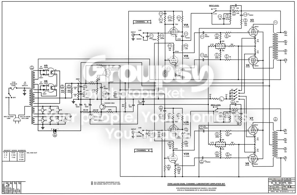
 
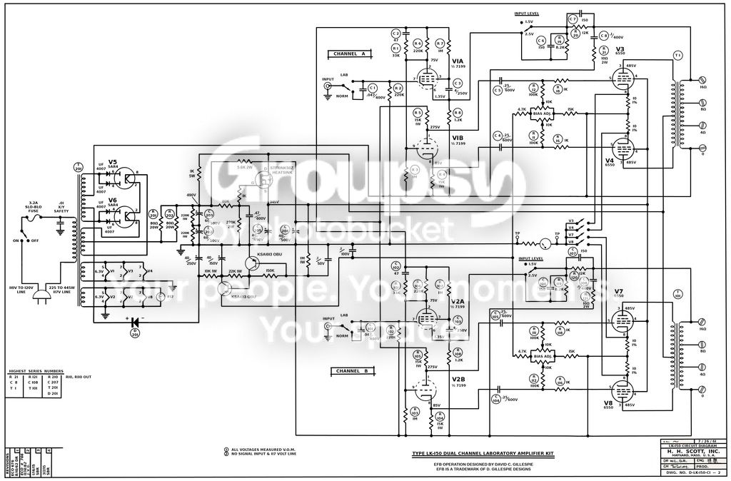
It has been pointed out to me that due to the corrupted condition of the Nov. 62 schematic I started with, that there was a numbering error in the 7199 pins.

Revised schematics attached.

Edit: some voltage errors were brought to my attention, schematic is now revised again:

LK-150_EFB_IB_schematic_Rev11_zpsqyzz4m81.jpg
 
Last edited:
Any more progress? I'm curious about how the mods turned out. Considering at least the independent bias on mine. And the digital meter.
 
Got sidetracked for a while. Need to repaint the transformers and get back to work on it.

I stole the independent bias circuit from Stu Hegeman's H/K Citation II, with some tweaks to keep the overall resistance in line with the original LK-150 design.
 
Thanks for the revised schematic. Interested to see how this project looks and sounds when finished.
 
Revised schematic. dcgillespie recommended a tweak to the power supply in a recent message.

LK-150_EFB_IB_schematic_Rev12_zps49igfczu.jpg
 
I've started working on the physical placement of components, taking the modifications into consideration. Last thing I need to do is whip up a little DC power supply to take the place of the pilot light. The digital meter can take a wide range of input voltage, but it needs at least 4.5V to work.
 
I've actually started assembling things!

Instead of the digital meter, I discovered that Scott ordered their analog bias meters from Japan (like the knobs), and that the same basic meter was used as a tuning meter for years in a lot of Japanese tuners and receivers. Just needs a different face, and a proper compensating resistor to set the full scale point to 1V (the 10 ohm cathode resistors making the math easy, 75mA = .75V). That project was a little bit more generic than a lot of the work done here, so I gave it its own thread in DIY: http://audiokarma.org/forums/index....amp-with-a-dead-unobtanium-bias-meter.751114/

Now I just need to decide which face design I'm going to use.
 
Geez Sam,still not done and lifes slipping by.I recently put together an ancient pair of JBL C-37's in utility cabs and have been running my Scott LK-150/LC-21 pre steady for the last couple weeks ..that amp needs to be heard!!
goodluck getting it up and running

Hunter
 
Face installed in meter body with permanent double-sided tape, meter body installed in chassis. The scale is crisp and sharp in person, I think my camera tried to focus on the chassis and got the meter just a tiny bit out.

Meter_installed_sm.jpg

I still need to make some gold anodized plates so I can fix that ugly mess on the front and properly re-label the bias switches from per channel to individual. The artwork is done (pictured earlier in the thread), just need something to put it on.
 
Sam ,or Hunter, Can you measure your chassis for me? I am building a 290(from a 272), and I think the 150 chassis may be close enough to build a 290 on.I started a thread on the 290, and I haven't had any responses on the dimensions.
 
Sam ,or Hunter, Can you measure your chassis for me? I am building a 290(from a 272), and I think the 150 chassis may be close enough to build a 290 on.I started a thread on the 290, and I haven't had any responses on the dimensions.
My lk 150 chassis measures 11 1/4 " wide x 2 3/8 " high x 14 1/2" inch's long

hunter
 
Last edited:
Back
Top Bottom