• The move to the new server is done. There are some software and database maintenance updates in process. This has us passing the hat around to help out. We appreciate any donations. Seriously, even a dollar helps. The payment page may be found here - https://www.audiokarma.org/support.html

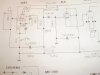
SE 811 amp schematic...

Easiest way to get more gain without really changing circuit - use CCS instead of plate resistor of first tube. Look at IXYS devices. You only need two resistors with them to add CCS to your circuit.

Looked it up,, seems like a chip of some kind... Seems it works kinda like a gas regulator tube, but for a constant current supply, instead of voltage...

I keep running into this schematic I used, but never in English,,, Maybe I have this amp built as well as possible, considering all the info I've read about how difficult this tube is to use for audio and it does sound good as is,,, I'm sure the exact rated OPT would help some...
I don't have enough experience to modify the circuit too much on my own, and I'm not really convinced it needs FB, as it seems to be very clear, with no change in distortion thru out the volume range...

Regards,
John
 
you could duplicate the existng 6SN7 stage and just put that ahead of the current circuit. That would get you another triode worth of gain, should be plenty if you want to add a feedback loop. Some single ended amps don't use one though, so it may not be necessary.
 
you could duplicate the existng 6SN7 stage and just put that ahead of the current circuit. That would get you another triode worth of gain, should be plenty if you want to add a feedback loop. Some single ended amps don't use one though, so it may not be necessary.

Just not exactly sure how to connect teh two sections...
However, you are right, I put a pot between the output tx secondary and driver, and it just lowered the volume, as expected, but didn't change the tone or improve sound at all, that I could tell... So FB most likely won't add anything to this design,,, It sounds very similar to teh 6BG6 amp, in the few hours I've run it,,, and the 811 is super cool looking!

Regards,
John
 
Last edited:
I just built the 811/6L6/6SJ7 schematic on post #7, used a 6BG6 instead, as I have a few... This one sounds even better than the first one(811/6V6/6SN7)... Used the same OPT for both... I think this is the amp I will pursue to use the 811s... There are a couple of cap values missing, one in particular is in the FB loop... I used a 330pF and a 1K pot,,, Adjusting the pot doesn't seem to make much difference in sound, gain or distortion, so I guess the cap value is way off...
I'll try to post the schem link here if anyone wants to comment,,,

http://tomo.fine.to/V.World/I-811A-J.html
Thanks,
Regards,
John
So did you use triode or pentode (like in your link) in first stage?
 
Pentode 1st stage(6SJ7), as in the schematic... The only changes I made so far, are 6BG6 2nd stage, and matched 50ohm resistors instead of teh pot on the 811...I also used an input cap,,,
I have teh FB loop disconnected for now, until I get it sorted out,,, may not even need it...

Regards,
John
 
Pentode 1st stage(6SJ7), as in the schematic... The only changes I made so far, are 6BG6 2nd stage, and matched 50ohm resistors instead of teh pot on the 811...I also used an input cap,,,
I have teh FB loop disconnected for now, until I get it sorted out,,, may not even need it...

Regards,
John
I think this first stage is a limiting factor. Triode with CCS load will be way better - much more linear.

As for the unmarked capacitor in cathode of first tube, put something like 1000uF.
 
I think this first stage is a limiting factor. Triode with CCS load will be way better - much more linear.

As for the unmarked capacitor in cathode of first tube, put something like 1000uF.

Thanks for the info, I'll try that cap... I'm not opposed to changing or experimenting with this design,,, do you have a schem or drawing of the 1st stage you would use? I'm not against using a different tube there either,,,Not really a fan of the metal tubes,,, I believe 6SJ7 is available in a glass bottle also, I don't have any...

Regards,
John
 
Here's something you can try:

Replace the 6SJ7 with half a 6SL7; you will need to rewire the socket.
Replace the 43 ohm resistor with a 390 ohm resistor.
Replace the 8.2k ohm voltage dropping resistor with a 1k ohm resistor.

You are looking for 240V on the B+ side of the 82k ohm resistor and 150V on the plate of the 6SL7. There should be 1.5V on the cathode of the 6SL7.

You will have to adjust the feedback resistor for best sound.
 
Thanks for the input,,, The other 811 amp I mocked up used a 6SN7 1st stage,,, This one(6SJ7), has enough gain,,, wouldn't a 6SN7 section be a closer match than 6SL7? That schem is on post #14...
With your changes, does the 300K, and .33uF that are connected to G2 stay, or are they just screen supply for the pentode?
I put in the 1000/uF cathode cap, also...

Here's a pic of the proposed changes, for 6SL7...

Regards,
John
 

Attachments

  • P8160013.jpg
    P8160013.jpg
    51 KB · Views: 52
Last edited:
With the 6SL7 the 300k resistor and the .33uF cap are no longer needed and should be removed. The reason for the 6SL7 was to give you a triode with enough gain for considerable feedback; otherwise the 6J5 is fine.

I must have had a brain fart because I forgot that the 6SJ7 can be turned into a 6J5 (half of 6SN7) by triode connecting the screen grid. IOW, there is no need to change to a 6SN7 or 6J5, just triode connect the 6SJ7. To do so remove the 300k resistor and .33uf cap and connect pin 6 to pin 8 with a 100 ohm resistor. This should work well if you don't need much feedback. You will need to change the plate and cathode resistors too. Try a plate load of 47k and cathode resistor of 820 ohms. You want a B+ of 240V (more if you reduce the power supply series resistors) with 90V on the plate and 2.75V on the cathode.

No problem, I am glad to have the input,,, maybe I'll get to the point where I can figure it out myself!
I switched it over to 1/2 of a 6SL7, (that's what you meant to use correct? You just mentioned 6SN7)... It sounds about the same as before(6SJ7)... I have a 1K pot in place of the FB resistors, and it doesn't change the gain, or sound... May need one with a larger range, or no FB at all, would be best...
Probably better off using a triode rather than strapping a pentode... Plus I get a glass tube instead of the silly cans!

Here's some preliminary readings, without any tweaking...
Plate V: 6SL7=150V, 6BG6=252V,,, 811=371V,, 6SL7 K 1.5V,, 811 Grid26V...

Thought I had a problem with the 100uF cap not charging, but it turned out to be an intermittent 811 tube, replaced it, and all is well,,,,, So far!
Here's the updated schem...
Thanks again for the input,,, Confirm your mod is 6SL7 or 6SN7, I have plenty of both...

Regards,
John

 

Attachments

  • P8170014.jpg
    P8170014.jpg
    45.4 KB · Views: 35
Last edited:
Ultimate tuning should be done with spectrum analyzer (either hardware or software). It is hard to recognize minor variations of distortions by listening alone, more so without quick side by side comparison.
 
Just tried a 6SN7 1st stage,,, amp sounds clearer, plate V dropped to 81V with no other changes to the circuit,,,, I'm thinking that's the tube you meant to use...

Regards,
John
 
Just tried a 6SN7 1st stage,,, amp sounds clearer, plate V dropped to 81V with no other changes to the circuit,,,, I'm thinking that's the tube you meant to use...

Regards,
John
81V is too low. Target should be 120-130V. You need to reduce plate resistor accordingly. You may try to simulate circuit first using TubeCAD or LTSpice.
 
Post #52: your operating points for the 6SL7 are correct.

Post #54: If you like the 6SN7 better, then you could focus on dialing in the operating point for that tube. As forP1 stated, the plate voltage is somewhat low. Morgan Jones experimented and found that lowest distortion was with 6mA plate current. Using the schematic from Valve's World we see that the voltage on the 6L6 is 240V and that voltage is all you are going to get unless you parallel another resistor to the 8.4k and tap off the 380V B+ in which case you can get and easy 350V.

Here's the simplest solution for no feedback:

Plate resistor: 33k ohms
cathode bias: red LED

Operating points of the 6SN7: Vp = 81V; Ec = 1.4V; Ip = 4.85mA
 
Thanks guys,,, I'm no audio tech, let alone EE!!!! Never able to figure out teh simulators,,, However, I'll try to bring the 6SN7 into the specs you posted,,,
Again, I really appreciate teh help...

Regards,
John
 
Post #52: your operating points for the 6SL7 are correct.

Post #54: If you like the 6SN7 better, then you could focus on dialing in the operating point for that tube. As forP1 stated, the plate voltage is somewhat low. Morgan Jones experimented and found that lowest distortion was with 6mA plate current. Using the schematic from Valve's World we see that the voltage on the 6L6 is 240V and that voltage is all you are going to get unless you parallel another resistor to the 8.4k and tap off the 380V B+ in which case you can get and easy 350V.

Here's the simplest solution for no feedback:

Plate resistor: 33k ohms
cathode bias: red LED

Operating points of the 6SN7: Vp = 81V; Ec = 1.4V; Ip = 4.85mA


I can easily raise the 6L6 Vp, the PS is capable of more, its on a variac, now...

FB,,, 33k Rp for 6SN7 ? Where does teh red LED go? replace 1k, 390 resistors?

Operating points/6SN7: Vp is 81V now, not sure what you mean here....
Thanks...

Regards,
John
 
If you want to do away with the feedback you can replace the plate resistor on the 6SN7 with 33k ohms. Remove the 1k and 390 ohm resistors and put in a cheap red LED which will drop about 1.4V for the tube's bias. Don't forget to put it in the correct way so that it turns on. If it doesn't light it is probably in backwards; the cathode goes to ground. With 240V B+, 81V on the plate, and a 33k ohm load, the tube 6SN7 will conduct 4.85mA. If you don't want to mess with the LED you can remove the 1k resistor and just use the 390 ohm resistor (330 ohm would be better and you can even try a 270 ohm but that restricts your input voltage) and bypass it with a 220uF cap. Using the LED does away with the cap.

If you raise the B+ on the 6L6 you might upset the bias on the 811 so it is better to leave it as it is unless you are up for fiddeling with the bias on those two tubes.
 
Update:
I lowered the B+ resistor to 5k, and with 33k 6SN7 Rp got 150V,,, so, replaced 33k w/47k and get 128V 6SN7 Vp, 290V 6BG6 Vp, and 376V 811Vp...
The cathode V is 4.6,,, and 811 Grid is 32.4VDC, is that too high? I think schem calls for 811 Grid 24VDC...
Thanks,

Regards,
John
 
Back
Top Bottom