

You are using an out of date browser. It may not display this or other websites correctly.
You should upgrade or use an alternative browser.
You should upgrade or use an alternative browser.
Register to hide this ad

Ed Dumas
Member
First, this amp is the dirtiest that I have ever seen on the inside. I believe it has lived with cats for many years and then lived in the garage, or something like that. There will need to be some serious cleaning as I go along.
Now, as I looked it over, I see that there are some suspect issues besides the caps. First, transistors TR101 to TR108 all look very suspect. These transistors all have corroded black legs, and I am wondering if they should be replaced. TR101 to TR104 all use 2SA902-F and the TR105 to TR108 all use 2SC1328-T. Jeromach, can you recommend the correct part for these. Do they need to be matched like the double transistors?
Second, resistors R501 and R502 legs both look very dirty, like something was burned on the legs where they go through the board. Note that they are close to the filter caps, so heat may have affected them. They are listed at 82Ohm 3W Fuse Type-Metallic Film. I cannot seem to find a replacement for those. Any suggestions?
Finally, several diodes also look kind of suspect with black corroded legs. These are listed as SVD10E1 and SVD6B6CTA-2. Do you have any information on replacement parts for these?
Now, as I looked it over, I see that there are some suspect issues besides the caps. First, transistors TR101 to TR108 all look very suspect. These transistors all have corroded black legs, and I am wondering if they should be replaced. TR101 to TR104 all use 2SA902-F and the TR105 to TR108 all use 2SC1328-T. Jeromach, can you recommend the correct part for these. Do they need to be matched like the double transistors?
Second, resistors R501 and R502 legs both look very dirty, like something was burned on the legs where they go through the board. Note that they are close to the filter caps, so heat may have affected them. They are listed at 82Ohm 3W Fuse Type-Metallic Film. I cannot seem to find a replacement for those. Any suggestions?
Finally, several diodes also look kind of suspect with black corroded legs. These are listed as SVD10E1 and SVD6B6CTA-2. Do you have any information on replacement parts for these?
Last edited:


jeromach
With sufficient thrust, ducks fly just fine
Did the amp play when you bought it (on both channels)? If so, I wouldn't be bothered too much about the resistors (apart from R509 that may have a cracked coating) and about the diodes.
The SVD6B6CTA-2 is the main rectifier in a TO-3 casing, it should last forever if not hit by lightning or something similar. It could be replaced by a present day bridge rectifier (example; http://www.futurlec.com/Diodes/BR86pr.shtml).
The SVD10E1 are regular rectifier diodes, you could replace them for cosmetic purposes if you want. I used 1N4002 for that purpose once, perhaps today I would come to another choice, but at that time they sufficed and will do now too.
When I worked on this amp, I took it apart completely, except for any wiring. It's a pita to remove and again mount the power transistors, due to little washers and nuts and additional heat shields that are more or less impossible to remount when the amp is not taken apart. The same goes for desoldering the wires and soldering them in again, another pita and it can be avoided by just leaving them in place and work on the boards like that.
As you could see from the previous picture the TR101 - TR108 can be replaced by KSA992(FBU) and KSC1845(FTA). Please note that the red dotted ones should be matched.
Below I will post some images so you can see for yourself.
The SVD6B6CTA-2 is the main rectifier in a TO-3 casing, it should last forever if not hit by lightning or something similar. It could be replaced by a present day bridge rectifier (example; http://www.futurlec.com/Diodes/BR86pr.shtml).
The SVD10E1 are regular rectifier diodes, you could replace them for cosmetic purposes if you want. I used 1N4002 for that purpose once, perhaps today I would come to another choice, but at that time they sufficed and will do now too.
When I worked on this amp, I took it apart completely, except for any wiring. It's a pita to remove and again mount the power transistors, due to little washers and nuts and additional heat shields that are more or less impossible to remount when the amp is not taken apart. The same goes for desoldering the wires and soldering them in again, another pita and it can be avoided by just leaving them in place and work on the boards like that.
As you could see from the previous picture the TR101 - TR108 can be replaced by KSA992(FBU) and KSC1845(FTA). Please note that the red dotted ones should be matched.
Below I will post some images so you can see for yourself.


Ed Dumas
Member
Did the amp play when you bought it (on both channels)?
No, there is no output on both channels. I tried firing it up, and all I got was noise from pretty much every switch and dial on the unit. That tells me that these need to be seriously cleaned.
Thank you for those photos. That is very helpful, especially the photo of how you took the amp completely apart. That is a very good idea, since there is so much cleaning that needs to be done on this amp. With it all apart like that, I will be able to get to everything that needs to be done.
Here are two photos I took this morning. The first is of the rectangular resistors. You can see the crap at the bottom of the legs where they are connected to the board. Maybe I will try cleaning them off first before I replace them. Maybe that will suffice.
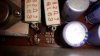
You will also see what looks like hair amongst burned grease, or something like that. The line over the resistor at R509 I believe is a hair (cat?) covered in the same crap. If I do the cleaning first, then I will know if it needs to be replaced or not.
Also, here is a photo of the diodes I mentioned before.
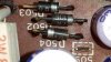
Do you think that the black legs is a bad sign? You can also see closeup of the burned black gook on the white ceramic resistor leg at the top left corner. Much to do!
jeromach
With sufficient thrust, ducks fly just fine
The black stuff on the diodes never hurt anything as far as I know. I'd just clean the board and leave them as they are.
Did the relay click when you switched it on? If yes, there might be nothing too seriously wrong, if not, then especially all transistors and diodes should be checked.
Did the relay click when you switched it on? If yes, there might be nothing too seriously wrong, if not, then especially all transistors and diodes should be checked.
Ed Dumas
Member
The relay did click on when I powered it up. There was no output though, except for some noise from almost all the switches and dials. There was a fairly thick layer of corrosion on the input jacks, though. I tried to clean some off when I tested the amp, but maybe I still did not get a decent connection there. Once I have that unit cleaned, re-capped and re-assembled, I will test it again and see if that fixes the problem. Do you have a good way to get corrosion off of input jacks?
I am also still fairly certain that at least one of the power transistors is reading at zero. I tested it attached to the board, and that is what I got. Maybe I should remove them, though, and test them again for a more accurate reading?
If that is not the problem and I need to test transistors and diodes, do they need to be removed from the board before testing them? Can I use wires with little clips connected to my plug-in transistor tester?
I am also still fairly certain that at least one of the power transistors is reading at zero. I tested it attached to the board, and that is what I got. Maybe I should remove them, though, and test them again for a more accurate reading?
If that is not the problem and I need to test transistors and diodes, do they need to be removed from the board before testing them? Can I use wires with little clips connected to my plug-in transistor tester?
jeromach
With sufficient thrust, ducks fly just fine
Er... not really, I never actually had real corrosion on input jacks. If it IS corrosion, I'm afraid you'd need to replace them. If it is just staining you could try to use car or brass cleaner or something similar, but it will be some job...
I think it depens on what kind of transistor tester you have wheather the transistors can stay in the board or not. I have several testers myself. The DMM diode test functionality I guess should work when the dut (device under test) is in the board. An Atlas tester sometimes works, but not always and can give wrong results when the dut is in the board. Same goes for the cheap Chinese testers. But I mostly use a Huntron tracker which is accurate with the dut in the board.
Testing the power transistors through the wiring is not a good idea, there might be a breach somewhere. Taking them out is not a bad plan, you then also can apply a fresh layer of cooling paste.
I think it depens on what kind of transistor tester you have wheather the transistors can stay in the board or not. I have several testers myself. The DMM diode test functionality I guess should work when the dut (device under test) is in the board. An Atlas tester sometimes works, but not always and can give wrong results when the dut is in the board. Same goes for the cheap Chinese testers. But I mostly use a Huntron tracker which is accurate with the dut in the board.
Testing the power transistors through the wiring is not a good idea, there might be a breach somewhere. Taking them out is not a bad plan, you then also can apply a fresh layer of cooling paste.

Blue Shadow
Waiting for Vintage Gear from this century
In your testing did you use the preamp outputs and power amp inputs to find if the problem was isolated to one or the other?
Ed Dumas
Member
In your testing did you use the preamp outputs and power amp inputs to find if the problem was isolated to one or the other?
No, but that is a very good idea. Once I have it all back together and have done the re-capping, if it is still a problem, I will certainly use that as a way to isolate the issue. I have temporarily stopped work on this amp for a few days, as my guest band from Holland is here now. I will be back at this again in about four days, and then have it together again maybe a week after that. I know, I am slow, but I am not a pro!
I had a thought about the "slime" (grease?) all over the amp. I think it is years of collected tobacco smoke (ugh). When I first started cleaning some metal brackets, I got that smell from it. After an hour or two, I finally put it together as to what could cause this. So, Jeromach, I used your idea of removing the entire amp from the case in order to complete the cleaning better. It just seemed to be a good idea, and it is working well so far.
When I first pulled the amp out of the case, I even found some blades of grass inside! Poor amp, it has really had a rough go of it. If I get this baby working again, I figure I should be able to do just about anything, like create fire with two sticks! ;-)
Anyway, I have cleaned half of the switches now. They seem okay to open up, and they are definitely black on the inside. But with a small old toothbrush and some chrome cleaner like you suggested, they seem to come up pretty quickly. I wonder if that black is also tobacco, because it seems to come off pretty easily.
I am looking forward to getting back to it in a few days! Thanks for the tip on the pre-amp/power-amp. Good idea. That reminds me - I must also pull those bridge links and clean the heck out of them!
Ed Dumas
Member
I am back! Now that my guests have departed, I have spent some time on the remaining switches. All is good there now. Bit of scrubbing, but it went okay. I think with practice I am getting better at this. 
I am beginning to ordering process for the electrolytic caps. I see that caps C115 to C118 require a 110uF polar cap at 10V (or higher of course). I have checked Mouser and Digikey, and neither carries an audio grade radial cap at 110uF at any voltage. Jeromach, how did you solve this problem when you did your SU8600?
I am beginning to ordering process for the electrolytic caps. I see that caps C115 to C118 require a 110uF polar cap at 10V (or higher of course). I have checked Mouser and Digikey, and neither carries an audio grade radial cap at 110uF at any voltage. Jeromach, how did you solve this problem when you did your SU8600?


MacPhantom
Guest
Really? I never heard these brown caps to be any troublesome, but of course I do believe you.

Not ALL of the 'brown capacitors', just the Tantalum ones, replace with low leakage electrolytic or better, 'film' capacitors if you can.Really? I never heard these brown caps to be any troublesome, but of course I do believe you.
Tantalum capacitors last a long time but can go bad. Their main problem is that they have a fairly high 'infant mortality' rate i.e. in new gear where they can go short circuit and make a mess, going short circuit later on is rare unless they get reverse voltage applied - beware.
Ed Dumas
Member
Well, er.... 110uF does not exist as far as I know
Yeah, that is what I thought too. Dummy me, though. I did not check for errors before I asked you that question. Must have been late last night.... Anyway, the error was mine. I copied it from the manual incorrectly, and did not confirm on the board. It should be 100uF. Oh well! Sorry about that.
Don't forget to replace the brown tantalum caps, C101 and C102.
Thanks! Will do. Anything else that I should note?
Similar threads


- Replies
- 3
- Views
- 2K


