• The move to the new server is done. There are some software and database maintenance updates in process. This has us passing the hat around to help out. We appreciate any donations. Seriously, even a dollar helps. The payment page may be found here - https://www.audiokarma.org/support.html

Transmision Line ?

Keilau another good thread on damping material in the link below.

http://www.audiokarma.org/forums/showthread.php?t=189662

Thank you for the link to the discussion on damping using polyester fiber. Ken Kantor cited the work by John F. O'Hanlon which echos the work by Bradbury. There is marked difference in fiber glass vs. polyester as expected. Even though O'Hanlon was dealing with closed box enclosure. It helps us to understand not all acoustic stuffing material are created the same.

I have tried changing stuffing materials in a small bookshelf speaker with a 6.5" woofer. I tried long fiber wool, fiber glass and polyester fiber. I honestly could not hear any difference due to 2 factors. #1, I do not have a trained ear. #2, the speaker is a cheap Realistic brand. O'Hanlon's paper is very helpful to understand that.

I also tried to replace the polyester batting by long fiber wool in a Whardefale aperiodic enclosure with twin 7" woofers. It had drastic improvement in both the extend and control of the low end even I can hear. It is the Wharfedale MT-138 model.

I.M. Fried chose drivers in his T-lines that have a large Vas. which contradicts the guidelines of others in the link below of DRIVER SUITABILITY.
The various 10" drivers I.M.Fried used have a Vas of 170-180 liters, a low mass cone, low Qts. and a decent Xmax approximately 8-10mm.

http://brinesacoustics.com/Pages/Quarter_Wave_Resonators.html

I do not know the background of the Brines owner. His data showed that the enclosure without long fiber wool stuffing behaves just like a resonant Helmholtz air column. He called that a "Classic TL", but nothing even remotely looks or sounds like the Bailey design.

To get the non-resonant (no ringing) bass loading, Bailey ended up with a design that rolls off at a very slow 6 db/octave, see Figure 9 in the original Bailey paper. On the other hand, the Brines designs, including his "classic TL" rolls of at 12 db/octave or higher like all vented enclosure design.

I.M Fried tried to design the transmission line enclosure as originally intended. Mr. Brines tried to designed a resonant vented enclosure. There is no surprice that their choice of driver are different. I do not have a lot of insight into Mr. Fried's selection, but his recommendation in driver selection made a lot of sense to me. I have 3 data points. The KEF B139B-SP1044 in the Bailey design has a Vas of 164 litres. I used a Philips AD-10100 10" woofer based on the Jastek recommendation in the Audio Amateur which has a Vas of 111.4 litres. I recently acquired a pair of Peerless 850146 10" which has a Vas of 144.4. The Peerless 850146 seemed to be popular among TL speaker builders. These values are at the high end of today's commercial products, but not as high as I.M. Fried's selection. He might have custom made woofers designed for him.

It points out to the need of a driver database that would be suitable to Bailey transmission line enclosure. We also need a reliable source of long fiber wool blanket.
 
Last edited:
These values are at the high end of today's commercial products, but not as high as I.M. Fried's selection. He might have custom made woofers designed for him.

It points out to the need of a driver database that would be suitable to Bailey transmission line enclosure. We also need a reliable source of long fiber wool blanket.

Yes Fried had many of his drivers custom made.

These links are other threads about the Fried designs.

http://www.audiokarma.org/forums/showthread.php?t=504495

http://www.audiokarma.org/forums/showthread.php?t=552484

http://www.audiokarma.org/forums/showthread.php?p=7602420#post7602420

http://www.audiokarma.org/forums/showthread.php?t=567441
 

sm19422, thank you for the links and many interesting reads in the links and their sublinks.

I was able to listen to the IMF loudspeakers in high end audio store many years ago and met Bud Fried once at a Minnesota Audio Society meeting some 40 years ago. A poor graduate student cannot afford them. I was always intrigued by his approach to speaker design. His transmission line design is as close as to the sound that Bailey descirbed as I've ever heard, without using long fiber wool. Are there any engineering blog on how the open cell foam works and how to select the right kind of foam for speaker stuffing or aperiodic plug. I have seen a few posts on selecting aperiodic plugs from commercial products, but nothing on how or why.

I also wonder if anyone can come up with a simple figure of merit to help selecting speaker stuffing material. The large diameter fiber, high specific gravity long fiber wool works good for transmission line. The small diameter fiber, low specific gravity fiber glass works well for closed box. The large diameter fiber, low specific gravity polyester/Dracon does not work for TL/closed/vented designs. The thorough academic study done by Bradbury and O'Hanlon are very important and enlightening. But the average DIY speaker builder need some simple guidance they can follow. There are too many cookbook information that are misleading without sound basis. See one example of comment on the Vance Dickason's loudspeaker book on page 54 on the subject of crossover design.

http://www.theaudiocritic.com/back_issues/The_Audio_Critic_17_r.pdf
 
attachment.php


Roger Sanders has also marketed his T-line and electrostatic speaker designs.
I remember and still have his many writings that appeared in Speaker Builder magazine.

http://sanderssoundsystems.com/technical-white-papers/56-transmission-line-white-paper


Meadowlark Audio which sadly closed used T-line designs.

http://www.6moons.com/audioreviews/meadowlark2/kestrel2.html
 

Attachments

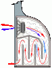
  • tranmissionlineweb.gif
    tranmissionlineweb.gif
    6.6 KB · Views: 84
Last edited:
Nice C-atle... never heard of Chapman, and now I have! See we all learn things!!!

I read this review of the T8 and this guy mentions the Bass from his "metal/rock" perspective. The Bass in the T8 only goes down to 28Hz +/-2 so my first response was that maybe they don't go as low in that "Bottom Octave" as a TL, but they sound like they are still pretty dynamic.

This is an interesting subject! In his review he talks about the difference between the "Front Firing" Tetons and the "Side Firing" Chapmans. In my write up of the comparison of my TDL's to my KEF 107's, I noted that the Bass seemed more dynamic from the front firing TDL's, but that the KEF's seems to have more control and presence in the real low stuff. The KEF's, as many may know, are a Coupled-Cavity design, and my sense is they are NOT a "Dynamic Bass"!

Now, my definition of "Dynamic" and "Presence" in this case is that the TDL's seem to come at you with the Bass, whereas the KEF's just seem to "envelope" you with it. You don't quite know where it is coming from and it doesn't strike right at you, but aurally it's all around you and at the right times and notes seems to penetrate you with resonance. That's "the magic" of the big KEF's!

Thanks again for the Chapman reference... and if anyone can shed light on C-atle's question on what constitutes a "Compression Line", please enlighten us all! :thmbsp:


The chapman's are one speaker I might just pony up for at some point. I've heard one of the TOTL model playing mono off a cary monoblock and the sound was, incredible. The sense of space, and presence from 1 speaker just blew me away. And it was Louis armstrong singing non-the-less.
 
It is on page 164, Equation (4), the definition of theta.

You will not be matching Bradbury's calculation until you correct this typo. I have been wondering whoelse noticed it. I tried to replucate Bradbury's calculation on a HP programmable calculator after I read the paper and found that I did not get the same numbers as he did in 1976. I found the typo when I went through the derivation of his equations and reconciled the calculation. I concluded that it was a typo made by the Journal of AES, not a mistake by Bradbury.

Through this process, I saw the beauty of Bradbury's work. The typo was a small, but critical one. I will post the detail when I come home from work tonight. Now, I have pointed out where and what the typo is. Anyone wants to beat me to post the detail?

It is one of the most significant and elegant piece of work on the theory of transmission line enclosure. It showed both qualitatively and quantitatively how the sound wave propagates in a long fiber wool filled line by test and analysis. It provided a sound guidance on what to look for if you want a substitue for the long fiber wool. What is your opinion of this paper? (Question to everyone) I have not seen many comment in other posts, except one person who said that it does not work.

Yes, I understand that the Bailey and Bradbury works are NOT complete. They did not model how to couple the driver to the enclosure, thus, leaving the actual design as mostly empirical. The work by Bailey and Jastak (1973 Audio Amateur) filled an important gap.

Trying to model the TL enclosure as a resonant, vented box so that it can be coupled to a driver model is like cutting the foot to make the shoes fit.

I derived a T&S type complete model including the driver for a lossless and a simple lossy model starting in 1978, finished the paper in 1980 as a Major Qualifying Project at WPI. I wrote a computer program in very buggy DEC FORTRAN that ran on a DEC 10 or 20 in batch mode. It had a lot of problems with complex math and they complained about how long my runs took. I had a hard enough time finishing the lossless model so I did not spend a lot of time on lossy. I spent probably 5 to 10 times as much time on this paper as I did for my Master's Thesis at Cornell. My project adviser was good about helping me with the basics, and he certainly knew acoustics and transmission line theory, he taught it for both RF and power engineering in addition to teaching the Audio Engineering class at WPI. The computer model had good agreement with the lossless experimental line and with the lossy line at least around L/4. I did see a reduction in the speed of sound with damping material, I would say due to adiabatic to isothermal shift. I'm not a thermo expert but both my brilliant project adviser, and my dad, an MIT chem eng thermo expert said yes that was the reason, as do most other authorities on the acoustical behavior of air with a loss material added. I don't believe the moving fiber theory, if it happens at all it is a small effect, certainly foam doesn't do this.

I'm an EE with an emphasis in analog and digital design and communications systems. I was a teaching assistant at Cornell for microwave lab (transmission lines) and took several courses in microwave design in the hopes of learning more about TLs and cavity resonators.

I'm fairly certain that the people at Bose read my paper, I interviewed with them in 1980 and in response to their Bose hype I said read my paper. I went on to graduate school.

I was not at all impressed with Bailey's article and work.
I'd say that the papers from Stromberg-Carlson Co. in 1936 showed better experimentation and understanding
of TL fundamentals. They were Radio design engineers and they probed down the line measuring SPL, this is
how you do a VSWR measurement with a voltage probe in RF design. Woah! and they did it in 1936!

OK guys, how do you find the L/4 frequency in a lightly damped TL through measurements of the input impedance? What do you expect to see in the woofer's near field SPL at L/4? Yes, quiz time.
 
Last edited:
Check out this from PMC...

tran_cutaway.jpg


The main driver is placed at one end of the TL, which is heavily damped with absorbent acoustic material. The most predictable and accurate absorber is a highly specified foam material that took a vast amount of R&D to derive the correct formula of profile, pore size and density of the polymer. The foam, probably the least visually dramatic of the components is tremendously important. It has to absorb all the upper bass frequencies and allow the lower frequencies to exit the vent at the far end of the line in phase with the main driver. It must also be exactly specified to ensure a consistent and balanced backpressure on the driver by interfacing smoothly with the column of air within the line. With too higher damping, the driver cannot move freely enough, and conversely too little damping produces a lack of control and the result is a LF response similar to that of a regular ported design.

When this equilibrium is achieved between length of line and the acoustic absorbency, the air density increases by up to 30% making the 'effective' line length far greater than it's physical length. This backpressure holds the main driver in a vice like grip and the control is effective over a huge frequency range, reducing unwanted cone movement which lowers audible distortion. This lack of harmonic distortion in the LF creates superb midrange clarity as it eradicates the effects of masking. The consistent air loading also facilitates full audible bandwidth at all monitoring levels allowing for extended periods of monitoring without the risk of fatigue.

So, how are Vented and TL systems similar, their behavior around box tuning and L/4 are analogous. How are they different? TLs have powerful repeating resonances at multiples of the L/4 frequency in both the acoustical input impedance and the acoustical transfer function as frequency increases until more complex modes come into play. What is PMC doing there? They are making the TL act more like a vented system by damping those higher resonant modes but allowing the lowest L/4 mode through minimally damped. This most closely approximates a well designed vented system.
 
OK guys, how do you find the L/4 frequency in a lightly damped TL through measurements of the input impedance? What do you expect to see in the woofer's near field SPL at L/4? Yes, quiz time.

Pete you should also read this thread. :)

http://www.audiokarma.org/forums/showthread.php?t=616146

One way would be to use warble tones and measure the impedance at the woofer terminals.

http://www.audiokarma.org/forums/showpost.php?p=8184415&postcount=122

I.M Fried flattened the impedance in his subwoofer designs using his series resonant crossover circuit.
A 12mh 14 gauge air core inductor and 150-200mfd cap is one example of this.

The added Re. of the inductor does raise the driver Qts. and also serve to flatten the impedance curve and pad down the subwoofer sensitivity to the satellites at the same time for a flat response.
 
Last edited:
Back
Top Bottom