• Check out the Annual AK Secret Santa exchange Program, signup before November 23rd in the AK Charities & Christmas forum!

Troubleshooting CD Players

The disc table has a tube on the bottom. That's where you want to pry to move the table up. There is a gap between the tube part and the mechanism, which is too large to simply pry it up with a screwdriver, so find a piece of wood to insert in the gap as a spacer and put the tip of the screwdriver on top of it, to pry up the disc table. Don't try to pry at the flat part that the CD sits on or you will distort the table and the disc will wobble!

View attachment 2100272
Thank you for your insight! I am going through a grinding issue with my Marantz CC4300 right now. It the "table" that black piece that lifts up into the CD hole your white arrow is pointing to? When you say "tube on the bottom" do you meant the metal rod that is the axel for that black piece where your arrow is pointing?
 
Thank you for your insight! I am going through a grinding issue with my Marantz CC4300 right now. It the "table" that black piece that lifts up into the CD hole your white arrow is pointing to? When you say "tube on the bottom" do you meant the metal rod that is the axel for that black piece where your arrow is pointing?
The table is the piece the Cd sits on. The tube I am talking about is the neck underneath the table.
 
The table is the piece the Cd sits on. The tube I am talking about is the neck underneath the table.

I believe you are a genius sir. I couldn’t get the table to slide up on the rod it is mounted on. I was putting a good amount of torque using the flathead screwdriver and a wood shim but I felt like something would break if I applied more force. I did confirm
That it was a height issue by stacking two CDs neatly on top of each other and it played dead silent that way. So what I did was I made 4 tiny (>1/4 in square) four-ply pads of masking tape and carefully applied those to the table:
nDFavR1.jpg


It now plays dead silent! I hope the hack lasts! I appreciate your help and all you’ve contributed to this thread!

tvJLcCS.mp4
 
I think in the case of your unit the problem is the suspension is sagging and you need to put washers underneath the rubber springs.

I believe you are a genius sir. I couldn’t get the table to slide up on the rod it is mounted on. I was putting a good amount of torque using the flathead screwdriver and a wood shim but I felt like something would break if I applied more force. I did confirm
That it was a height issue by stacking two CDs neatly on top of each other and it played dead silent that way. So what I did was I made 4 tiny (>1/4 in square) four-ply pads of masking tape and carefully applied those to the table:
nDFavR1.jpg


It now plays dead silent! I hope the hack lasts! I appreciate your help and all you’ve contributed to this thread!

tvJLcCS.mp4
 
Happy festivus to all.

Check pin 36. Should be around -27V.

I just realized the diagram in the service manual I have doesn't match the one you posted. Pin 62 was not vdd but happened to read < 5V, vdd pin 64 did as well but no pins read -27.
 

Attachments

  • スクリーンショット 2021-12-26 19.50.26.png
    スクリーンショット 2021-12-26 19.50.26.png
    687.1 KB · Views: 7
Happy festivus to all.


I just realized the diagram in the service manual I have doesn't match the one you posted. Pin 62 was not vdd but happened to read < 5V, vdd pin 64 did as well but no pins read -27.
It would be helpful if you repeated more information from your posts; MFR, Model, symptoms. It's a long thread with many posts and issues.
 
Apologies, I was afraid of cluttering the thread and thought the link to the past quote might be enough.

Onkyo Liverpool C-200

Buttons intermittently trigger the neighboring one, e.g. track 7 triggers track 8 etc. Bad buttons/solder has been ruled out.

It was suggested to use a scope to check voltages on the chip for the buttons. About half of the pins including vdd read < 5, a good number read nothing, a few show what looks like static, and rst and sc show a square wave with wavy tops and bottoms.

service manual http://freeservicemanuals.info/en/servicemanuals/viewmanual/Onkyo/C200/
 
Apologies, I was afraid of cluttering the thread and thought the link to the past quote might be enough.

Onkyo Liverpool C-200

Buttons intermittently trigger the neighboring one, e.g. track 7 triggers track 8 etc. Bad buttons/solder has been ruled out.

It was suggested to use a scope to check voltages on the chip for the buttons. About half of the pins including vdd read < 5, a good number read nothing, a few show what looks like static, and rst and sc show a square wave with wavy tops and bottoms.

service manual http://freeservicemanuals.info/en/servicemanuals/viewmanual/Onkyo/C200/
Pin 60 should read Vcc (5V). Make sure it's clean with no ripple on the scope trace.
Start with pin 62 and press 5, 6, 7, 8, 9, and then 0. You should get a pure DC voltage each time, a different voltage for each button. Determine which button(s) give the wrong results. Check the voltages as you press the buttons.
Pin 38 is the reset and should be a constant 5V.
 
The pause button triggers the track forward button and gives the same voltage. How is this fixed? My uninformed guess is to replace one or more resistors around R708 (if I had the correct ones on hand I would have tried this before replying).

The track 7 button triggers track 8 but gives a different voltage that that of the track 8 button. I don't know where to refer to determine whether or not the track 7 button's voltage is correct. If it is correct, that means the cause of that button's malfunction is not a voltage discrepancy?
 

Attachments

  • スクリーンショット 2021-12-28 16.31.09.png
    スクリーンショット 2021-12-28 16.31.09.png
    650 KB · Views: 8
The pause button triggers the track forward button and gives the same voltage. How is this fixed? My uninformed guess is to replace one or more resistors around R708 (if I had the correct ones on hand I would have tried this before replying).

The track 7 button triggers track 8 but gives a different voltage that that of the track 8 button. I don't know where to refer to determine whether or not the track 7 button's voltage is correct. If it is correct, that means the cause of that button's malfunction is not a voltage discrepancy?
First thing to do is measure the resistors. I would also recommend taking the board out and cleaning it with alcohol in case someone spilled something in there, contaminating the board. Check the switches with your meter on ohms, a dirty switch will add resistance and confuse the microprocessor.
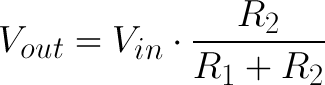
As for the correct voltages, the resistors make up a voltage divider, along with the 7.2K resistors located at the microprocessor on the schematic going from the processor to 5V. The resistors in the switch matrix are the bottom resistor in the divider, going to ground. To calculate the voltage out of the divider, use the formula:

511968d9ce395f7c54000000.png

Where R2 is the bottom resistor in the divider, going to ground. Vin is 5V. R1 is 7.2K.
 
Last edited:
The resistors' measurements matched the schematic.

I have to figure out the best way to clean the board, a cloth will get ripped apart and qtips will take forever, and I don't have a dish of a size that won't waste a lot of alcohol giving it a bath.

Sorry for this question, switches are just on and off devices? So they should read zero resistance when pushed and infinite resistance when not pushed?

The equation, R2 is the sum of the resistors in front of a given button? e.g. in the schematic, for pin 60, R2 is 0 for the play button, 1.5 for pause, 1.5 + 1.8 for up, 1.5 + 1.8 + 3.3 for down, and 1.5 + 1.8 + 3.3 + 8.2 for repeat?

 
The resistors' measurements matched the schematic.

I have to figure out the best way to clean the board, a cloth will get ripped apart and qtips will take forever, and I don't have a dish of a size that won't waste a lot of alcohol giving it a bath.

Sorry for this question, switches are just on and off devices? So they should read zero resistance when pushed and infinite resistance when not pushed?

The equation, R2 is the sum of the resistors in front of a given button? e.g. in the schematic, for pin 60, R2 is 0 for the play button, 1.5 for pause, 1.5 + 1.8 for up, 1.5 + 1.8 + 3.3 for down, and 1.5 + 1.8 + 3.3 + 8.2 for repeat?

1. Acid brush.
2. Yes. Since the resistors measure ok, it has to be contaminated board or dirty switches. They should read 0 Ohms.
 
Scrubbing the board had no effect.

I hate to post a sluice of possibly irrelevant details but for the sake of completeness please bear with the below. I apologize if it's unintelligible.

Switches: Each row and column in the schematic matrix I attached above is behaving similarly. I am trying to test the switches in circuit. For every switch whether functioning or malfunctioning, when I test horizontally it reads zero ohms. When I test vertically or diagonally it reads non-zero, an increasing value for each switch moving to the right in the matrix row. For example left most button switch is 3.5 ohms, next switch to the right is 5.5, next to the right is 9, etc.

I had previously swapped out one of the malfunctioning switches but that has no effect (though I imagine it's possible that the replacement could also be bad).

Voltages:
Start with pin 62 and press 5, 6, 7, 8, 9, and then 0. You should get a pure DC voltage each time, a different voltage for each button.

I didn't quite observe this, I previously elided for the sake of brevity. When I touched a microprocessor pin the voltage went to 5V. Keeping the probe attached, the voltage dropped a given amount when I pressed a button corresponding to the current pin. The voltage drop decreased for each button moving to the right in the matrix row. What I recognized as irregular was that the pause button's voltage drop did not match the drop of the other buttons in its matrix column.

I just noticed that the malfunctioning buttons are--perhaps coincidentally--all of the ones in column 2 of the schematic matrix (pause, clear, track 2, track 7).
 
I just noticed that the malfunctioning buttons are--perhaps coincidentally--all of the ones in column 2 of the schematic matrix (pause, clear, track 2, track 7).
This is a clue! Well, it should be a clue, but on the schematic the switches in this column have nothing in common.
Check the switches. You noticed that in the horizontal direction the switches measured 0 ohms. Those pins are jumpers. You need to measure the vertical direction and push the switch at the same time.
 
Thank you for keeping on emphasizing checking the switches. I changed one switch that had a weird ohm reading and then deoxited all of the switches, now two are misfiring very occasionally but this is good enough for me, I suppose if I deoxit another time or two that would get them fixed completely.

If the people who suggested switches months ago when I first posted about this deck are still reading this thread, I apologize for not listening then. At that time I replaced one switch and it didn't fix anything so I thought that ruled out bad switches, but it turned out the replacement switch was bad...

The moral of the story is when you get suggestions on this thread, make sure you actually follow them properly!
 
To clean the switches I inject Deoxit into the switch at the actuator, it works it's way into the switch from there. Then I work the switch a bunch of times. If you want to replace them, Digikey has push switches. You have to measure the height of the actuator and the pin spacing.
 
Denon DCD-910

On an 80 minute disc the player will konk out on the tracks around the last 10ish minutes, the sled will move to the track but will then return back to home either immediately or after a number of seconds. Then it will try again a few times before giving up and stopping. There is no disc wobble or rubbing. I oiled the sled rail. I can't see any damage in the worm gear.

To a previous question with a similar problem (page 27) it was suggested to adjust the tracking and focus offsets. How do I use my scope to do this? I know where the offset resistors are.

Also this was suggested:
Excessive runout can make the outer tracks unreadable on a long program disc. Check for crud on disc hub area and the hub.

What is the "disc hub area" and "hub"?

service manual (can't find one in English...)
https://www.hifiengine.com/manual_library/denon/dcd-910.shtml
 
Denon DCD-910

On an 80 minute disc the player will konk out on the tracks around the last 10ish minutes, the sled will move to the track but will then return back to home either immediately or after a number of seconds. Then it will try again a few times before giving up and stopping. There is no disc wobble or rubbing. I oiled the sled rail. I can't see any damage in the worm gear.

To a previous question with a similar problem (page 27) it was suggested to adjust the tracking and focus offsets. How do I use my scope to do this? I know where the offset resistors are.

Also this was suggested:


What is the "disc hub area" and "hub"?

service manual (can't find one in English...)
https://www.hifiengine.com/manual_library/denon/dcd-910.shtml
Usually when there is a problem playing the last tracks on a CD, it's because the bearing on the disc motor is dry. Apply a few drops of light machine oil to the top bearing on the disc motor.
 
No difference after oiling the disc motor.

I found there is a consistent failure timepoint, in case that is a sign of anything (72 minutes plus minus 10 seconds). Letting the CD play to 72 minutes or starting play at any point after 72 minutes results in the failure described above.
 
Back
Top Bottom