• Please note that Audiokarma will be offline briefly for updates early on Monday morning, September 28th.

Tube Power Supplies a Different Approach!

No SET, the hi Vs were/are factory and after I refurbed. The 100ohm is intact and in spec, as is the 180 ohm bias R. The elevated V actually starts at the 6CA4 output before the 100ohmer. Im gonna explore the rect tube(new one on order), and test it for "goodness" on both mu and em testers to see how it looks. Maybe it's normal. Ive not done ANY R bypassing yet. Its still morning and not dressed yet, just been thinkin alot and readin and lookin. It keeps me on my toes learning stuff like this. It's just facinating/interesting stuff. Ill report on the tube test results.
 
No SET, the hi Vs were/are factory and after I refurbed. The 100ohm is intact and in spec, as is the 180 ohm bias R. The elevated V actually starts at the 6CA4 output before the 100ohmer. Im gonna explore the rect tube(new one on order), and test it for "goodness" on both mu and em testers to see how it looks. Maybe it's normal. Ive not done ANY R bypassing yet. Its still morning and not dressed yet, just been thinkin alot and readin and lookin. It keeps me on my toes learning stuff like this. It's just facinating/interesting stuff. Ill report on the tube test results.

Sounds like that would require another tranny! At least all this has you thinking!:scratch2::thmbsp:
 
No SET, the hi Vs were/are factory and after I refurbed. The 100ohm is intact and in spec, as is the 180 ohm bias R. The elevated V actually starts at the 6CA4 output before the 100ohmer. Im gonna explore the rect tube(new one on order), and test it for "goodness" on both mu and em testers to see how it looks. Maybe it's normal. Ive not done ANY R bypassing yet. Its still morning and not dressed yet, just been thinkin alot and readin and lookin. It keeps me on my toes learning stuff like this. It's just facinating/interesting stuff. Ill report on the tube test results.

Everything sounds normal to me! that just the way a resistor input supply works a choke input is the same way!

Whats your AC secondary voltage on the amps transformer.

Check this out and the price! They offer covers too!

http://www.antekinc.com/details.php?p=46

Dave Conrad on this thread has a couple of them and they work and sound great! he has an awesome DCR of just 13 ohms in his 300B power transformers!
 
Last edited:
I want to build a completely transformerless amp some day. Can you imagine a 50 or 60 watt tube amp that weighs about 10 pounds.:eek: I wonder if I could get the PS quiet without any iron (chokes)?
 
Everything sounds normal to me! that just the way a resistor input supply works a choke input is the same way!

Whats your AC secondary voltage on the amps transformer.

Check this out and the price! They offer covers too!

http://www.antekinc.com/details.php?p=46

Dave Conrad on this thread has a couple of them and they work and sound great! he has an awesome DCR of just 13 ohms in his 300B power transformers!

Tran. sec. reads 262 vs schem 260 so its spot on. Just tested the rect.(can't test gm, just em.) and it is in super fine cond at the 75% GOOD range. A spare is good to have.
Well it's good to know that all is well with the supply voltages. Was concerned about it since reading the first one and going "whoa"! Learning abit more every day. Just fyi, Im a 30yr retired tech from HP.
 
Tran. sec. reads 262 vs schem 260 so its spot on. Just tested the rect.(can't test gm, just em.) and it is in super fine cond at the 75% GOOD range. A spare is good to have.
Well it's good to know that all is well with the supply voltages. Was concerned about it since reading the first one and going "whoa"! Learning a bit more every day. Just fyi, Im a 30yr retired tech from HP.

HP Tech cool!

Would it be possible for you to post a schematic of your amp or a link to it!

A buddy of mine that's a Mechanical Draftsmen once told me real Engineers use HP Calculators! Ok so I bought one! as he used one at work a dozen yrs back or so for a $100 it still serves well! Lots of HP computers at work!
 
HP Tech cool!

Would it be possible for you to post a schematic of your amp or a link to it!

A buddy of mine that's a Mechanical Draftsmen once told me real Engineers use HP Calculators! Ok so I bought one! as he used one at work a dozen yrs back or so for a $100 it still serves well! Lots of HP computers at work!

Not too swift at the link bit but "magnavox friends" at yahoo groups has schems in the "files" for many mag amps. the 88xx schems has the 8802 in the 88xx series section. I think you can browse without signing up, but its free anyway. youu can save any pic to your pics folder.
You remember the HP35 then. 1st scientific calculator. Revolutionized calculating forever. I have an 11C and the anneversary 32S. sold all the rest for pennies on the $:tears:
Cheers
Pete
 
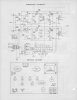
heres the 8802 schem.
8802 doesnt have the choke on the chassis, the 8801 does.
 

Attachments

  • Magnavox_88_Series_Page_2.jpg
    Magnavox_88_Series_Page_2.jpg
    80.8 KB · Views: 60
Last edited:
I remember my first calculator. It was a Texas Inst. and cost about 3 bills IIRC. Now I have a 50 dollar Casio fx 250HC Fraction that does more crap than I'll ever be able to figure out.:D
 
So, what are you thinking Jay? Mains voltage into a rectifier of some sort, giant bank of caps, maybe go balanced input into an OTL using enough of them to run the heaters on them right off of 115v?

A crapload of 6S19s 6AS7, 6336, or go crazy with some 6C33C. All of them thrive on low voltage and massive current. Sounds like a reasonable design if you want to watch your electric meter spin.
 
So, what are you thinking Jay? Mains voltage into a rectifier of some sort, giant bank of caps, maybe go balanced input into an OTL using enough of them to run the heaters on them right off of 115v?

A crapload of 6S19s 6AS7, 6336, or go crazy with some 6C33C. All of them thrive on low voltage and massive current. Sounds like a reasonable design if you want to watch your electric meter spin.

Yes, exactly along these lines. I don't think I'm smart enough to do the actual calculations for the impedance part of the design though.:no: I wouldn't even mind doing something that would run off a 220v line. I have a dedicated circuit for the stereo wall anyhow, so it wouldn't be a big deal to add another leg of power there. Then with a doubler, you could be around 450v or so, That would open up a lot of tube options. Heck you could even get a little crazy and use a big spray of 50EH or something like that. Some of those old higher voltage filament power tubes are cheap enough, I'd just have to look at some curves and pick a good linear one.:scratch2: Are you ready for another AK group design?:scratch2:
 
heres the 8802 schem.
8802 doesnt have the choke on the chassis, the 8801 does.

That is the same Maggie amp I've rebuilt 2 of here, and I redo the supply on that one as:

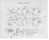
I go 30uf on the rectifier, 50ohm resistor, 30uf, 50ohm resistor, 330uf and feed the outputs
from there, then a 1k resistor and 20uf which feeds the screens and the front end tubes to.

After that setup you have a nice well filtered supply adding capacitance reserve where needed,
at the output tubes, end up with roughly 285v on the plates of the 6V6's an 265v on the screens.

I run 220ohm cathode resistors per "pair" of output tubes, bypass them with like 330uf on each set.
(that gets you around 33ma per output tube)

-----------------

No diss to SETS ideas but for me raising the voltage on 6V6's to at least 285v on the plate and 265v
on the screens is a marked improvement in the overall sound of the tube, so eliminating a resistor in a
supply that was low or near those numbers would obviously raise the voltage and improve the sound, IMHO.

(upping voltage further on 6V6's an EL84's is something they seem to like as well, this Maggie can't do that)

For me it's about a clean well filtered supply with plenty of capacitance at the output transformer connection.
(that's the type of supply that has served best for me, both in the sound department an quietness of an amp)

------------------------

I attached the modded supply I've done on that particular Maggie amp. :)
(Chokes would be better then resistors, but working within a budget/chassis restraints here on this amp rebuild)
 

Attachments

  • Magnavox_88__supply_mod.JPG
    Magnavox_88__supply_mod.JPG
    66.9 KB · Views: 71
Kegger, i'm now getting 270 and 265 respectivly on the plates and screens without doing anything so am approaching your V values, and the sound is great IMO. Im getting 24ma bias I per tube in stock config now but have a mod to implement in that area.
Thanks for the info. Im saving your schematic.
 
I use PSUDII to design power supplies or when re-working supplies in existing amps. It simulates most everything I throw at it with dead on accuracy to the milivolt. You can even calculate how much current your console amp's PT is capable of dishing out.
 
That is the same Maggie amp I've rebuilt 2 of here, and I redo the supply on that one as:

I go 30uf on the rectifier, 50ohm resistor, 30uf, 50ohm resistor, 330uf and feed the outputs
from there, then a 1k resistor and 20uf which feeds the screens and the front end tubes to.

After that setup you have a nice well filtered supply adding capacitance reserve where needed,
at the output tubes, end up with roughly 285v on the plates of the 6V6's an 265v on the screens.

I run 220ohm cathode resistors per "pair" of output tubes, bypass them with like 330uf on each set.
(that gets you around 33ma per output tube)

-----------------

No diss to SETS ideas but for me raising the voltage on 6V6's to at least 285v on the plate and 265v
on the screens is a marked improvement in the overall sound of the tube, so eliminating a resistor in a
supply that was low or near those numbers would obviously raise the voltage and improve the sound, IMHO.

(upping voltage further on 6V6's an EL84's is something they seem to like as well, this Maggie can't do that)

For me it's about a clean well filtered supply with plenty of capacitance at the output transformer connection.
(that's the type of supply that has served best for me, both in the sound department an quietness of an amp)

------------------------

I attached the modded supply I've done on that particular Maggie amp.
(Chokes would be better then resistors, but working within a budget/chassis restraints here on this amp rebuild)

Thanks Kegger for your input here.

Between the two schematics I can see what what was done.

But, IMO if you really wanted this amp to step up the pace a bit, for $29 I'd drop one of these in. Pretty Black steel cases are available for $18 put a small plate over the hole and bolt in.

http://www.antekinc.com/details.php?p=46

In addition your chassis probably has the room so add a second rectifier this transformer easily has the capacity for it and the amp will have some extra punch!

Ideas! I haven't even gotten started!

Cheers

SET12
 
PSUD2 is useless to the followers of the good doctor.

Now thats pretty funny :D

I'd be interested in reading their comments if you could direct a link to them that would be great!

I'm assuming your referring to Doctor Low Mu, correct?

I haven't read all of his comments or followers comments.

But yes, I do cater to a number of his views but not necessarily all of them.

I developed a number of my own ideas which are not design ideas in the classical sense as I call them.

This why I named this thread "Tube Power Supplies a different Approach"

I could possibly see why PSU might not be liked by them.

I don't use it myself, My interest is in sound not numbers.

And I suppose the PSU wouldn't like my supplies on my amps no doubt!

Especially with a GZ37 (slow turn on) rectifier feeding 1800uf's of electrolytic supply caps isolated with diodes to drop my supply noise over and then another 120 uf's of Poly caps all isolated again with diodes and all with nearly a zero DCR supply path to the rectifier.

You'd think it would be slow as molasses and if this was in a classical design it typically would be and it would sound very,very dark IMO.

But my supplies are as fast as a bullet, transparent as lit by the sun and with dramatic impact because of its energy reserves IMO. Its a phenomenal experience with people telling me that the amps got to be making more than 10 watts but that's what they are making!

Funny, I have been running these amps for 10 yrs with no issues at all.

But like I said I'm not concern with a 20-30yr life expectancy.

I had a 10% loss after 5yrs. If I get 10yrs thats fine for me and maybe its not for everyone. But I can tell you I have had some stunning listening sessions.

The amount of noise in a system a person can tolerate is a personal one IMO.

I can't tell you how many times I have heard super quite $100,000 systems sound sterile and lifeless yet I can tell you a tube amp with a little tube rush or hum for that matter is often more musical IMO.

I'm a subjective voicing advocate myself but thats a subject on to itself vs objective criteria.

I do believe there are things in audio not yet explained or measured.

An example maybe explaining the difference between two amplifiers abilities to display a sense of width and depth and height.

Or why can a 10 watt tube amplifier sound more dynamically extended in the frequency extremes than a good quality SS that technically has better measured bandwidth and ten times more power!

The list goes on and on!

In the end, its to each their own!

Cheers

SET12

 
Last edited:
Back
Top Bottom