• The move to the new server is done. There are some software and database maintenance updates in process. This has us passing the hat around to help out. We appreciate any donations. Seriously, even a dollar helps. The payment page may be found here - https://www.audiokarma.org/support.html

Tube tester: Sencore MU-150

This is really good. I think it would be a great addition to be able to order that panel and installed a digital meter.

Did you powered the ammeter via the second filament transformer, to get a separate supply from the main board itself?
Those things can't measure themself.
 
This is really good. I think it would be a great addition to be able to order that panel and installed a digital meter.

Did you powered the ammeter via the second filament transformer, to get a separate supply from the main board itself?
Those things can't measure themself.
Thank you, Brice! I powered the DPM through a small 120VAC to 12VDC converter that is tied into the main power cord. So once the unit is plugged into the wall, the DPM comes on, even if the Function switch is in the off position. As long as you do not mind me piggy-backing off your thread, I will write down some instructions, along with a parts list and a few links to get those parts.
 
Not at all. It's all about the MU150.

I see.
The native heater PT has a 12VAC tap, so adding a small bridge + 7812 + 2 caps and you have a independent 12VDC supply to power that ammeter.
It's all fun.
 
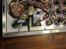
I was able to install the final part of my Sencore MU150 DPM solution. It is simply a daughter board that connects to the existing contacts for the digital panel meter. Shown in the last picture is the placement of the 120VAC to 12VDC converter that provides separate power to the DPM.
 

Attachments

  • IMG_8599.jpeg
    IMG_8599.jpeg
    222.9 KB · Views: 35
  • IMG_8600.jpeg
    IMG_8600.jpeg
    120.4 KB · Views: 36
  • IMG_8602.jpeg
    IMG_8602.jpeg
    203.2 KB · Views: 36
  • IMG_8601.jpeg
    IMG_8601.jpeg
    153.2 KB · Views: 37
I replaced my board with a new one I created. It is a copy of the original one. No changes, exept that I added
the splitted R6 to the board.
If you are interested, send me a note and I can provide the gerber files.
Ditt
You did a nice job on your version of the board Dieter! My MU140 is working great.
 
Hi Brice! I was excited to have someone point out this thread to me, and I'm very appreciative of all your hard work! Do you have a schematic available and or a component list? I used the Mouser Excel sheet but a number of components aren't on there which I didn't realize... it also looks like there may be some minor discrepancies and I want to figure out what I need to complete this. Again... THANK YOU!... it's a remarkable piece of work.

Paul
 
Hello Paul,

You are welcome.

I had to battle with the AK upload function to generate a small 1M file. What a pain.

Anyway, here is what I could find on the component list from my Mouser project. It's a good start for most but the resistors.

And the schematic.

I hope it helps.
Brice.
 

Attachments

Hello Paul,

You are welcome.

I had to battle with the AK upload function to generate a small 1M file. What a pain.

Anyway, here is what I could find on the component list from my Mouser project. It's a good start for most but the resistors.

And the schematic.

I hope it helps.
Brice.
Thank you Brice!

I'm deeply grateful and hate to impose but do you have a schematic of your circuit available? I'm very rusty and some of the specifics (such as which diodes go where) were hard for me to figure out from the PCB labels alone. Again... thank you!
 
I attached in a zip the schematic of the tester.
But from your question it seems that you are referring of the PCB layout and such?
Here it is.
 

Attachments

  • Sencore-MU150-V1_1.JPG
    Sencore-MU150-V1_1.JPG
    260.5 KB · Views: 16
Hi Brice... I hate to make you crazy with this, truly I do. The schematic I'm looking for is for your circuit, which I assume is not the same as the original? There are a few details that I'm confused by on the board... for example directly above the tube connections there are 3 pads that are not labeled. Are they unused? What are the values for CR12? That kind of thing. I apologize because these are probably obvious but I'm very out of practice. Once again... I appreciate your patience and all your help and I regret pestering you.
 
No problem.

They are pads to fit the original tube socket, well an attempt. They are not used, just grounded by the socket itself. I did not use them in my socket assembly.

Post #32 has most of your response I believe.
 
No problem.

They are pads to fit the original tube socket, well an attempt. They are not used, just grounded by the socket itself. I did not use them in my socket assembly.

Post #32 has most of your response I believe.
Thanks once again Brice... I missed that post! I'll re-read the thread and try to avoid pestering you ;)
 
Hello,

Thanks a lot for all the work into designing the new PCB. I recently bought Sencore MU150 tester and to renovate the tester I opted to replace the original PCB right away with the new updated version. I ordered the minimum of 5 PCB at JCLPCB and have 4 left now. Anyone who's interested in a PCB (shipping from France) may send me a PM. I also replaced the still good 5K/10K F-signal potentiometer with the 24 position switch if anyone is looking for one.
 
Last edited:
Hello! Quick Question. I finally tore into my Mu-150 and most all the tests were working well, most my tubes only tested to around 85 and would sometimes jump if I tapped the gauge. I'll get to calibrating and recapping soon. But I noticed I never had any deflection from my GM test. I pulled it apart and im missing a tube. I believe its an Ob2 Tube which is most likely why im having these issues, idk why or when it was taken out but im looking to replace it. Would it be best to buy an Ob2, or should I make a solid state regulator to put in its place instead?
 

Attachments

  • IMG_1297.jpeg
    IMG_1297.jpeg
    181.1 KB · Views: 12
  • IMG_1298.jpeg
    IMG_1298.jpeg
    157.6 KB · Views: 12
  • IMG_1295.jpeg
    IMG_1295.jpeg
    228 KB · Views: 11
Without the OB2, the 5KHz oscillator used for gm testing is not functioning, your tester indicates it.
I've used both, OB2 and SS regulator, and both work of course.

On the new board I posted, I remove the OB2 and used 3 serial zeners 36V 2W.

Do you have the plate with spring to hold the tubes in place? You might want to look into it as these sockets do not hold the tubes well.


MU150-plate.jpg
 
Without the OB2, the 5KHz oscillator used for gm testing is not functioning, your tester indicates it.
I've used both, OB2 and SS regulator, and both work of course.

On the new board I posted, I remove the OB2 and used 3 serial zeners 36V 2W.

Do you have the plate with spring to hold the tubes in place? You might want to look into it as these sockets do not hold the tubes well.


View attachment 3224207
Nope, no springs or shields, I went ahead and Ordered some PCBs. I went to calibrate it (I think I still can without the Ob2?) and it wouldnt go below 75ish on the scale. So i went ahead and decided to rebuild the whole PCB. So in a few weeks when its here ill be at it again lol.
 
Without the OB2, the 5KHz oscillator used for gm testing is not functioning, your tester indicates it.
I've used both, OB2 and SS regulator, and both work of course.

On the new board I posted, I remove the OB2 and used 3 serial zeners 36V 2W.

Do you have the plate with spring to hold the tubes in place? You might want to look into it as these sockets do not hold the tubes well.


View attachment 3224207
Brice with the new board will the 5KHz oscillator work for gm testing? I was a little confused in this post of yours
 
Hello,

Thanks a lot for all the work into designing the new PCB. I recently bought Sencore MU150 tester and to renovate the tester I opted to replace the original PCB right away with the new updated version. I ordered the minimum of 5 PCB at JCLPCB and have 4 left now. Anyone who's interested in a PCB (shipping from France) may send me a PM. I also replaced the still good 5K/10K F-signal potentiometer with the 24 position switch if anyone is looking for one.
Hello, Did you find a home for the F pot? I have a MU140 that needs one.
 
Back
Top Bottom